Introduction to Computer Networking
A computer network provides connectivity for end devices using network devices, protocols, and physical media so that remote resources can be accessed and shared among the users.
The end devices may be user computers or servers that are running applications or services.
The network devices may be switches, routers, or other message forwarding equipment.
Note
Switch vs Bridge: Throughout these notes, the term textbf{bridge} will be used to refer to the layer 2 devices rather than a switch (which is commonly used by manufacturers in a more general sense and not specific to their formal protocol support).
A set of protocols defines how data is exchanged between devices and on the physical media. Protocols define both the format and functional behavior of data exchanges. End devices send messages when requesting access to resources; similarly, they receive messages to respond to. The messages are bundled into data units per protocol format specifications. These data units are called packets.
Analogy: Protocol as the Language of Communications among Computers
Just as humans communicate in the language of their culture and have an alphabet,
grammatical rules, and communication etiquette, computers use specifically
formatted bit streams and processes to achieve data exchanges in networks.
Protocols define the format of a particular unit of bit stream, defined as
packets, to conduct communications, similar to words and sentences
in human languages. Protocols also define what packets will
be exchanged for which actions and how frequently, among what devices,
and in whatever particular formats. There are many protocols that run in current
networks.
A network graph is used to represent the connectivity of devices with each other
and is usually referred to as the network topology or just topology. In the
topology graph, network-device and end-device nodes are vertices and the connecting
physical media and logical links are edges. For example, Bridge1, Bridge2,
and Bridge3 are connecting devices device1 to device5 to each other in
the topology below.
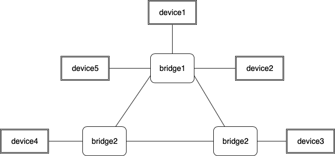
A network graph representation of devices (nodes) as vertices and links as edges.
Symbol |
Meaning |
|---|---|

|
end devices |

|
physical media |
Physical Media and Connectivity Concept
The physical media is where the electrical, electromagnetic and optical signals are used to transmit data such as the network electrical cables, optical fiber, and the wireless media. Every physical media has a specific protocol that defines the formatting of the sequence of bits for messages. The term on-the-wire is a convention used to refer to the physical layer protocol that defines the format for the transmission of sequence of bits.
The term layer 1, briefly L1, is used to represent:
All protocols, transmission techniques and signaling associated with
on-the-wirerepresentations of messagesThe physical connectivity graph of the physical media of a computer network: wiring, air
The electrical and electromagnetic signal exchange is a form of protocol too.
However, the L1 connection between two end devices is not a guarantee
that the devices can exchange data. That is, electromagnetic signals may be
sent and received between two end devices but there may not be actual communication
in the form of sent and received data.
Analogy: Hearing does not mean listening and communicating.
In a party, a group of people may be talking to each other. Even though sound of speech for each pair of talkers reaches the ears of all others, the actual communication happens between the pair of talkers in each case.
Logical connectivity refers to the ability for two end devices to exchange data.
Depending on the physical network media and the existing protocols in a network,
the logical connectivity may be realized as subgraphs of the L1 topology.
That is, the presence of a physical communication medium (L1) between two end devices
is required to realize communication at a logical connection through higher layer
(L2 and up) protocols. In this fashion, every higher layer logical connection may
restrict its immediate lower layer connectivity further.
Analogy: Logical Connectivity is Eye Contact
Human beings do not need to indicate they are about to talk to each other by saying anything like “Hello, I am about to talk to you, do you accept?”. Instead they make eye contact and start speaking: “Do you have the time?”, “Can you help me?”, “We have a very nice weather today.”, etc. In the case of computers in a network, each data exchange has to happen with some form of prelude “eye contact”. First, a pair of computers about to have a data exchange need to be able to send and receive electromagnetic signals. This is corresponding to them “seeing” each other and this is completely an electrical signaling and has no state for the pair of computers, namely, a physical connectivity. And then, the signals exchanged should indicate a precursor for “we are about to exchange data” which is analogous to the gesture during the eye contact made between two people, which is the logical connectivity referred to here. Finally, both computers are then ready to start the data exchange.
(a) The L1 Network Graph

(b) One Possible L2 Network Subgraph: The links between some device interfaces are enabled by L2 protocols and therefore, some devices are not connected at this logical layer.
Example Layering Concept: L1 and L2 connectivity
A long distance fiber-optic cable link between the continents Europe and North America
includes many repeater devices in between as shown in the L1 topology graph,
continents. The protocol and the repeater devices at L1 maintain an acceptable
power level for the transmission to be successful over this long distance. However, the
logical connectivity at L2 between the two ends of such a long distance link will
have no information about the repeater devices or the acceptable signal power levels
and the bit error rates. Once the transmitted signals are received, the sequence of bits
are the input data to the higher layer, L2, network protocol.
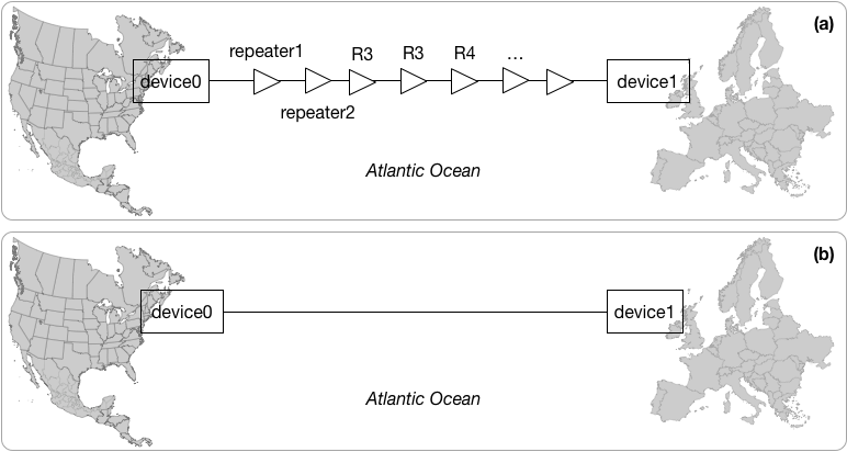
(a) L1 devices on a long-distance fiber-optic link between the continents Europe and North America (b) L2 link between the continents
Message, Data, Packet, Bits
Messages sent by end devices are formatted into bit streams with specific packet formatting of data representation per protocol. A message can be the request for a web page, an email text, a name to address resolution request, etc. Protocols define how the message will be encapsulated into a packet format with specific data fields such as the source and destination addresses, protocol type, length of message, the message itself, etc. Finally, the packets are sent as bit streams over the physical medium of communication for the network devices. Usually all data fields before the payload portion of a packet is called the header of a packet which includes an identifier for the protocol or the type of data that is inside the payload portion of the packet.