Basic Routing
How can hosts from different subnets send packets to each other?
Unless a different device in the network is able to route packets between the networks with different IP address ranges (subnets), direct connectivity provided by layer 2 (L2) will not suffice for the hosts in different subnets to be able to communicate with each other. This new device that handles routing between the subnets is called a router.
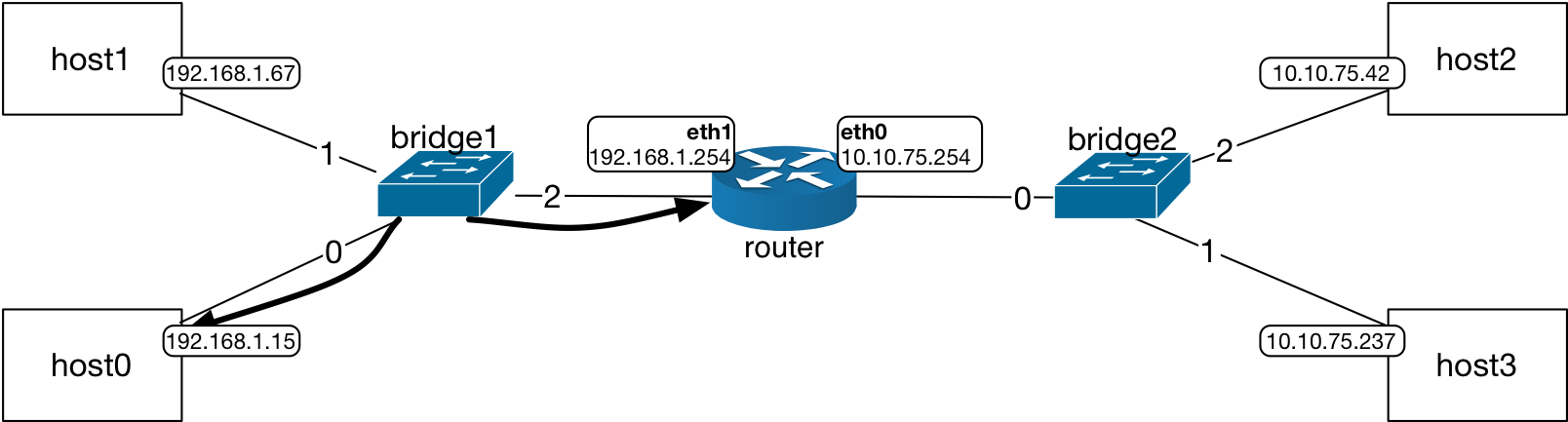
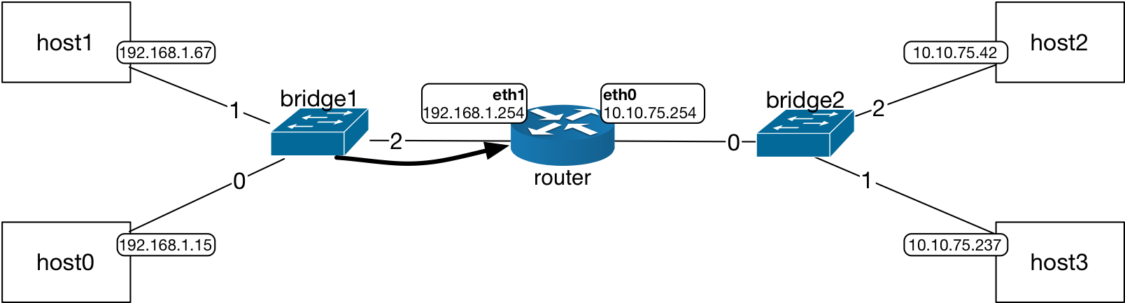
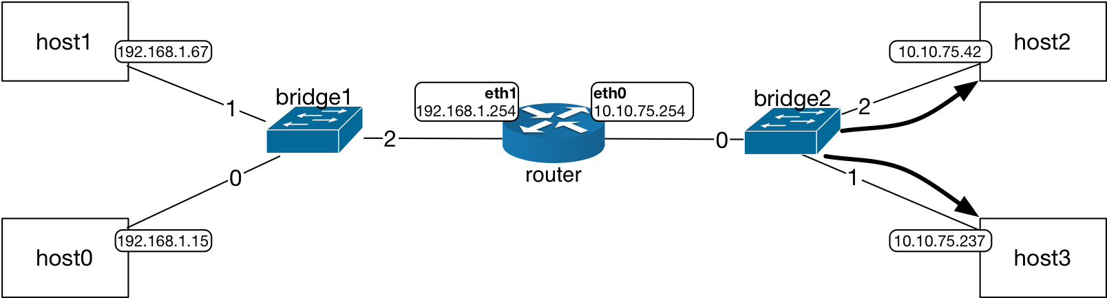
In the network topology shown below, host0 and host1 are in 192.168.1/24 subnet
and host2 and host3 are in 10.10.75/24 subnet.
Routers are layer 3 (L3) devices that forward packets between subnets.
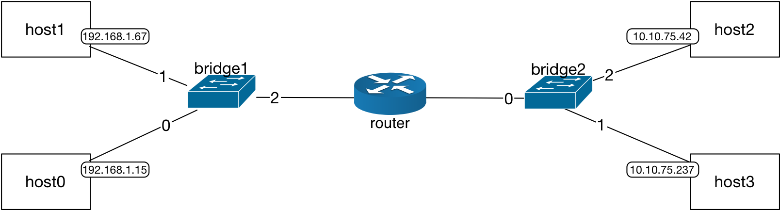
The router in this topology is configured with the route information for the pair of
networks that it is connected to: subnet 192.168.1.0/24 and the
subnet 10.10.75.0/24.
These configurations that are for forwarding of packets between subnets are called routes, namely,
the interface at which a destination IP address in a particular subnet can be reached along with
the nexthop (gateway) IP address (another router interface) that may facilitate the reachability (called routing) towards a
destination subnet where a particular destination IP address is in.
Analogy: Bridge, Router versus Train Tracks
The L2 network devices that are covered in this content, Ethernet bridges, are similar to how a particular train track may be switched to another track for a train based on its destination: Chicago train at a particular railroad switch in Dallas will be switched to (forwarded to) the track that goes towards Chicago. The L3 devices, routers, are handling the overall path of the packets. For the same train example, this corresponds to what station to station the train will have to go on the way to its destination in order to be able to reach that target. There is a specific set of stations that lead the path of the train towards Chicago for example.
The Internet Protocol and the other network protocols at L3 ensure the routes are shared between routers to facilitate the packets’ forwarding on the correct paths in the network.
Host Route Tables
Every host and router in the network has a route table.
The interface IP configuration of a host adds a route to the subnet
that the IP address is in. For example,
host0 and host1 interfaces are in the 192.168.1.0/24 subnet and
they can reach all other hosts
within that subnet using their eth0 interface through the layer 2 broadcast domain.
host0/host1 Route Table |
|
|---|---|
Destination Subnet |
Interface |
192.168.1.0/24 |
eth0 |
Similarly, for host2 and host3:
host2/host3 Route Table |
|
|---|---|
Destination Subnet |
Interface |
10.10.75.0/24 |
eth0 |
How does host0 send a packet to host2?
Since there is no route in host0’s route table to the destination IP address,
10.10.75.42, the packet to that destination IP address cannot be sent.
Please refer to the introductory section on the routing process.
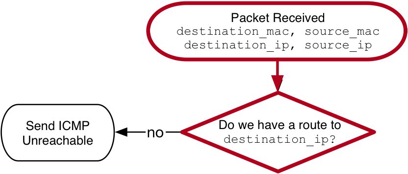
The first decision question in the routing flow chart
is: Is there a route to this destination?, which
is a check whether any of the destination subnets in the route table has the
destination IP address. In fact, among all destination subnets in the route
table, the one route that matches the destination IP address in the most
specific way is going to be chosen. Please see the section on
longest prefix matching for more information.
Nexthop IP Address in a Route
The route tables at the hosts may include an entry for a subnet other than
their own. These entries will have a nexthop IP address for the route.
For example, for hosts host0 and
host1 the nexthop IP address belongs to the router interface
within their subnet – 192.168.1.254 is in the subnet
192.168.1.0/24. The route indicates the interface to send the packets
to when the destination IP address of a packet is inside the subnet
10.10.75.0/24.
host0/host1 Route Table |
||
|---|---|---|
Destination Subnet |
Interface |
Gateway (Nexthop IP) |
10.10.75.0/24 |
eth0 |
192.168.1.254 |
192.168.1.0/24 |
eth0 |
|
This is true similarly for host2 and host3:
host2/host3 Route Table |
||
|---|---|---|
Destination Subnet |
Interface |
Gateway (Nexthop IP) |
10.10.75.0/24 |
eth0 |
|
192.168.1.0/24 |
eth0 |
10.10.75.254 |
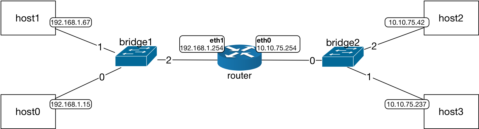
And, the route table at the router includes its own interfaces at the two subnets:
router Route Table |
|
|---|---|
Destination Subnet |
Interface |
10.10.75.0/24 |
eth0 |
192.168.1.0/24 |
eth1 |
The packet arrives at the router interfaces. Router then forwards packets to destination IP addresses in other subnets.
host1 sending a packet to the host2 at IP, 10.10.75.42, will look up
in its route table for the destination subnet. In this case, there is a
route to IP addresses in the 10.10.75.0/24 subnet:
Destination subnet:
10.10.75.0/24Interface:
eth0Nexthop IP:
192.168.1.254
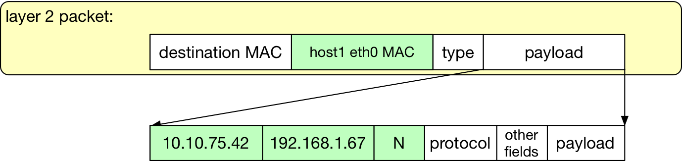
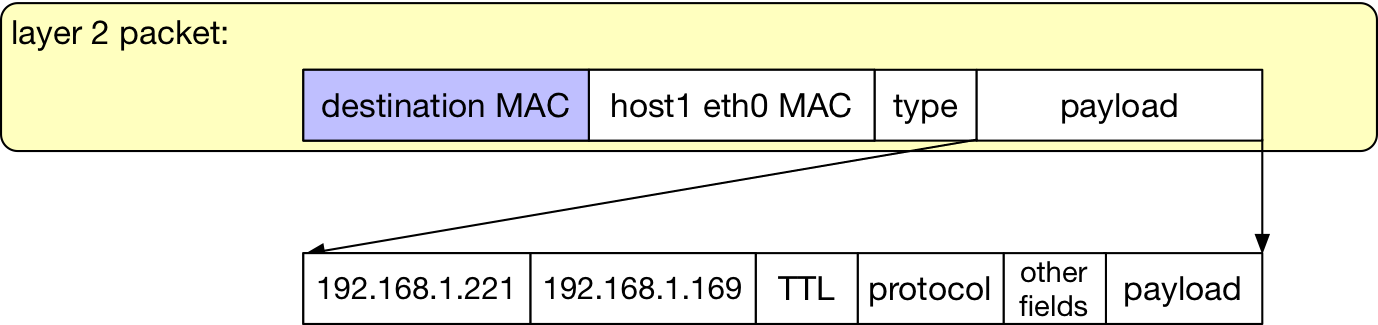
The packet that host1 sends will have the router interface MAC address in the destination MAC address field:

The L2 packet is destined to the router interface MAC address. The L3 packet has the destination IP address for host2.
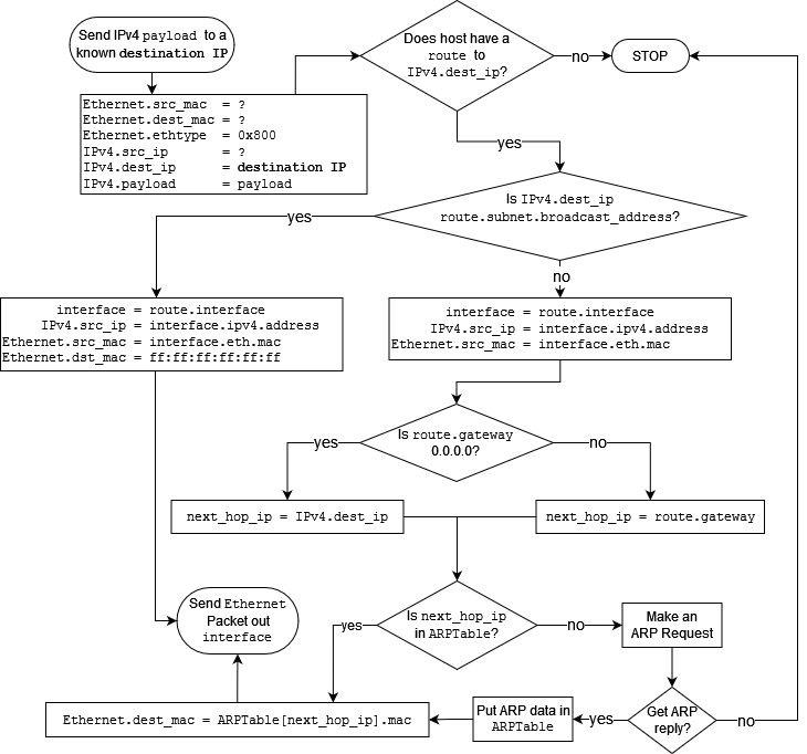
Routing Process Flow
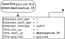
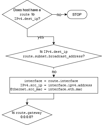
The routing process flow diagram is included below. Sending of an IP packet from a host for a given destination IP address involves checking destination IP address in the route table, checking the ARP table, and then preparing the packet’s L2 fields.
Deep Dive: Routing Process
If host1 in the topology is sending a packet to host2, it first checks whether there is a route for the destination IP address in its route table. There is a route to destination as indicated by the interface, subnet, and the nexthop IP address.
Then, host1 verifies that there is a gateway for the route, which is
the router interface IP address, 192.168.1.254.
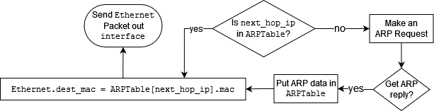
The MAC address for the nexthop IP address is checked in the host’s ARP table. Let’s assume that the host starts with an empty ARP table in this scenario.
host1 ARP Table |
||
|---|---|---|
MAC |
IP |
Expiration Time |
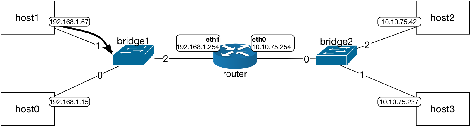
Since there is no ARP entry for the router interface in the host1 ARP table, host1 will send an ARP request.
ARP request packet has the router interface IP address in the request.
The ARP request packet will be broadcast by the bridge, sent on all ports, port 0 and 2, other than the incoming port, port 1.
The receiving interface at host0 will discard this message since its IP address is not matching the IP address in the ARP request. The router interface that receives this ARP request will reply with its MAC address directly back to the host.
router MAC Table |
||
|---|---|---|
MAC |
IP |
Expiration Time |
host1 eth0 MAC |
192.168.1.67 |
T1 |
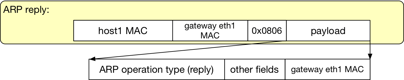
The bridge will forward this packet directly back to host1. The host will update its ARP table.
host1 ARP Table |
||
|---|---|---|
MAC |
IP |
Expiration Time |
router eth1 MAC |
192.168.1.254 |
T1 |
Now that the host has the MAC address for the interface which has the nexthop IP address, it can send the packet.
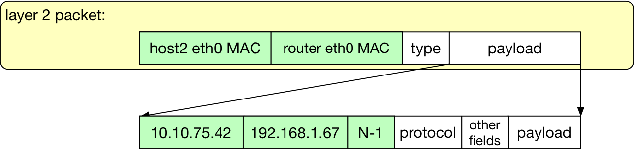
The packet sent by the host has the router eth1 MAC address in
the destination MAC address field. The payload part of the Ethernet
packet has an IP packet where the IP header includes host1’s IP address
in the source IP address field and host2’s IP address in the destination
IP address field. The time to live, TTL, field is set to a number, N,
which is dependent on the network configuration.

The packet as it left the sending host, host1.
The packet is forwarded directly to bridge1’s port 2 where the MAC address entry for router interface should be in the L2 table at bridge1.
The router interface checks the packet’s destination MAC address. Since
it matches the MAC address of the router eth1 interface, it strips off
the Ethernet header fields and starts to read the IP packet in the
Ethernet payload. The router checks its route table for a route for
the destination IP address in the packet, 10.10.75.42.
Attention
Routers are L3 devices. They process the header at layer 2 to determine whether a packet is destined to their network interface. When this is the case, they continue on to process the L3 packet encapsulated inside the payload field of the Ethernet packet. When forwarding the packet, they re-write the Ethernet header.
The destination IP address is in the 10.10.75.0/24 subnet. Router is
directly attached to the subnet on its eth0 interface. Router checks
the route to see whether there is a gateway. The route is composed of:
Destination subnet:
10.10.75.0/24Interface:
eth0
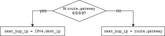
Since the route does not have a gateway, the next_hop_ip is set to
the destination IP address of the packet and then, the router process moves onto the
next stage to see whether this next_hop_ip exists in the router’s ARP
table. Router’s process from here on is the creation of the new Ethernet
header to forward the IP packet. If the MAC address of the host2 IP
address does not exist in the router ARP table, the router will send an
ARP request to resolve the host interface MAC address. The source MAC address
of the Ethernet header is the router’s interface MAC address for the route,
which is eth0. After the router interface receives the host interface MAC
address, it forwards the packet to the indicated interface which is eth0
in the route. Router updates the TTL field of the IP packet header to N-1.
Router forwards the packet on its eth0 interface.
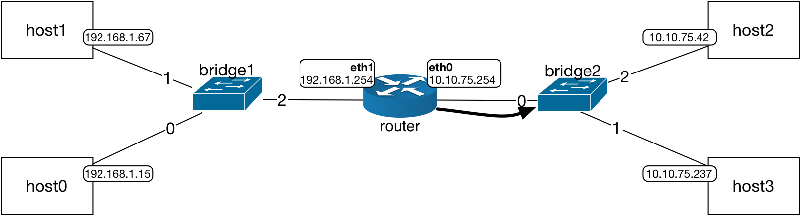
Since bridge2 also started with an empty L2 table, it will flood all of its ports except the incoming port with the packet received from the router.
Both hosts will receive this broadcast packet and they will strip off the Ethernet header to proceed to process the IP header of the packet. When host3 receives this packet, it will notice that the destination IP address does not match its IP address and drop the packet. When host2 receives the packet, it will match its own IP address to the destination IP address and continue to process the message in the packet.
IP packet receiving process flow chart:
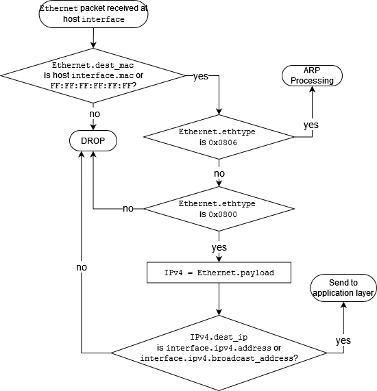
The key questions to keep in mind when tracing the process flow of routing are:
Is there a route to the destination IP address?
Does the route have a nexthop IP?
Is the nexthop IP address (this is an internal variable to the process flow of the device) in the the MAC/ARP table?
Attention
Nexthop IP Address
During the decision making process for routing, the nexthop IP address is used to determine the interface MAC address to send the Ethernet packet to. The packet’s destination IP address does not change. However, Ethernet header information for the destination is determined through this nexthop IP address.