Lab - 8: Routers
Objectives
The lab is on observations of:
Route tables in routers and hosts
Routing of a packet traversing multiple routers
Learn about the tool,
traceroute, that can display the IP addresses of the L3 devices traversed along the path to destination IP addressHow L1 loops in an L3 topology can provide redundancy for failure scenarios, such as a port of a router being disabled
Load Lab Network
Execute the commands to load lab topology:
%load_ext uhed
%lab
In order to conduct this lab, please pick Routers lab from the dropdown
menu and click on the Build Network button.
The topology that is reserved for this lab has three routers, routerA, routerB, and
routerC and three hosts, hostA, hostB, and hostC. The interfaces of the routers
that connect to each other and to the hosts are indicated on the topology graph that is
displayed on the lab notebook.

Lab Network Topology Reservation
Observation Guideline
The IP address assignment to hosts and router interfaces are displayed in the lab setup diagram below.
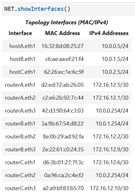
Open a terminal for each host, ssh into the host, identify their network interfaces, associated IP and MAC addresses.
On the lab notebook, execute
NET[<router-label>].getRouteTable()for each router:routerA,routerB, androuterCto retrieve the route tables at the routers in the network.
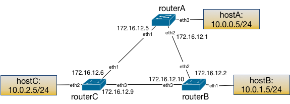
Lab network IP address assignments to the subnets.
Retrieve interface IP addresses of all nodes in the lab notebook:
Using the traceroute Tool
After marking all host network interface IP addresses, identify two hosts to examine an
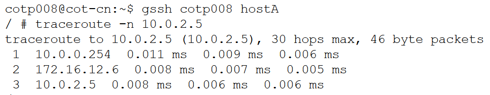
example traceroute output. For example, hostA issuing a traceroute to hostC
will expect to see traversing of routerA interface that connects to hostA as the
first hop. Consecutively, traceroute should report either one of routerC interface
on the edge between routerC and routerA or the routerB interface on the edge between
routerB and routerA. Since the shorter path is hostA to routerA to routerC and
then to hostC, the output should list those interfaces.
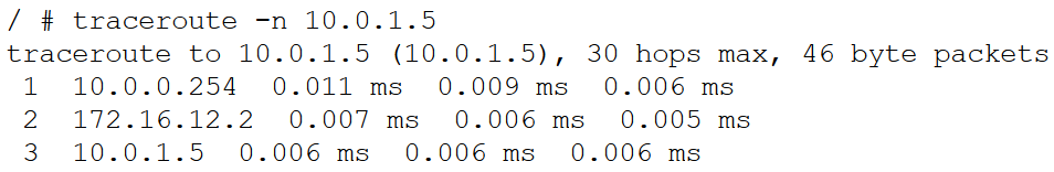
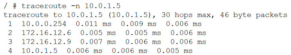
At hostA whose network interface IP address is 10.0.0.5, run the
traceroute command to determine the path the packets take on the
way to the destination IP address specified as target:
Examination of Route Tables
Routers keep a route table containing reachable subnets and interfaces through which those subnets can be reached. Subnets to which the router’s interface IP address assignments belongs are directly connected subnets; these directly connected routes are added at the time of IP address assignment. Following IP address assignment, the routers run a network routing protocol to determine their neighbors and what subnets may be reachable through their neighboring routers.
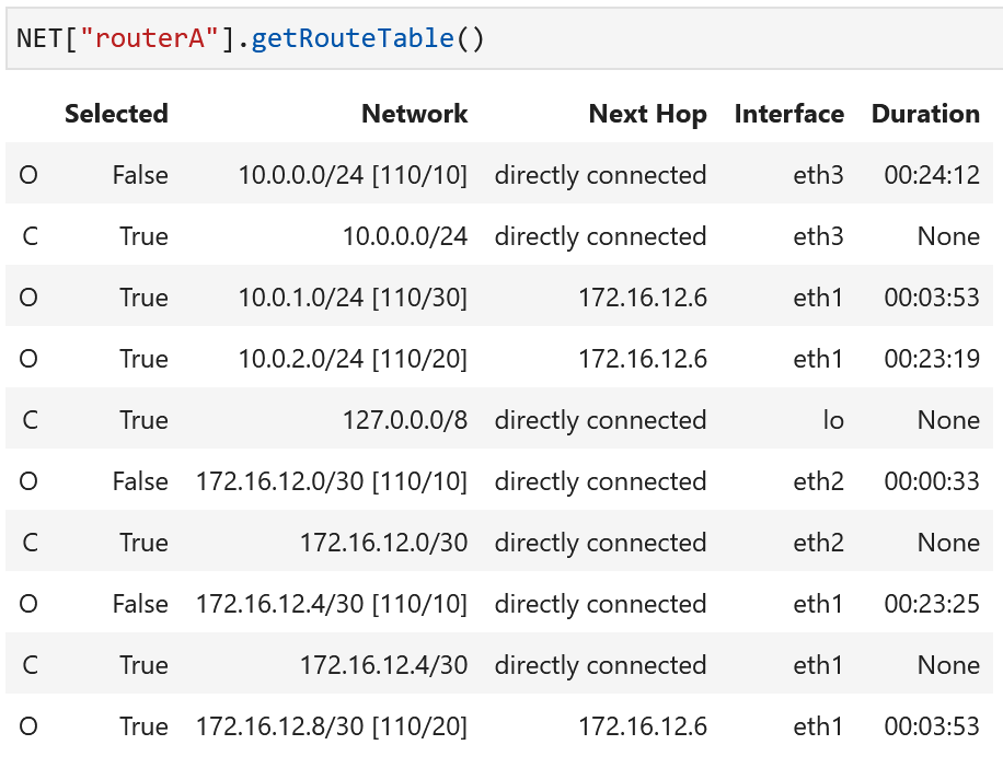
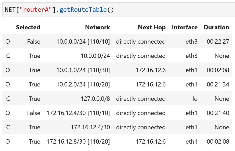
The topology has the following route table for routerA:

The route table at routerA lists all directly connected subnets, interfaces, and the
subnets that are reachable in this topology. The column for Next Hop lists the
gateways for routes, where available. The Interface column shows what interface to forward a
packet to when the packet destination IP address is inside the subnet listed in the column titled
Network. The letters O and C stand for OSPF (Open Shortest Path First - a network
routing protocol) and connected, respectively. The column Selected indicates what route
is active for the current ongoing traffic.
The host route tables can be retrieved by running NET[<host-label>].getRouteTable() in the notebook.
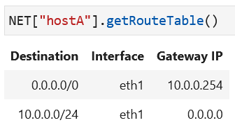
The host route tables include an entry for their own subnet since
they are directly connected. In addition, they have another
route entry for all subnets (0.0.0.0/0)
via the gateway (nexthop IP), which is the router interface IP address
that provides the reachability. The second route in this table is
sometimes referred to as the default route and its nexthop
IP address as the default gateway.
Attention
The route to all subnets: the destination subnet 0.0.0.0/0
includes all possible IP addresses in IPv4. When no other route entry
has a subnet that includes a specific destination IP address, the route
entry with this destination subnet, 0.0.0.0/0, is picked. Therefore,
this route entry is what a device may default to when no other
route provides reachability. Another way to think about this is to consider
this route as the shortest possible match for any subnet, so when a device is
looking for the longest-prefix-match, and no other route exists, this route
will always match.
After packets are exchanged using the ping and traceroute tools, the
ARP tables at the hosts and routers will be populated. Please verify by
running traceroute from the hosts and then retrieving the ARP tables.

The host ARP tables have an entry for their nexthop IP address (which is the IP address of the router interface).
The routers also have their ARP tables populated.
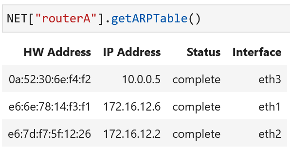
The router ARP tables have MAC addresses of interface IP addresses that are in the same layer 2 broadcast domain with their interfaces.
Disable a Port on a Router
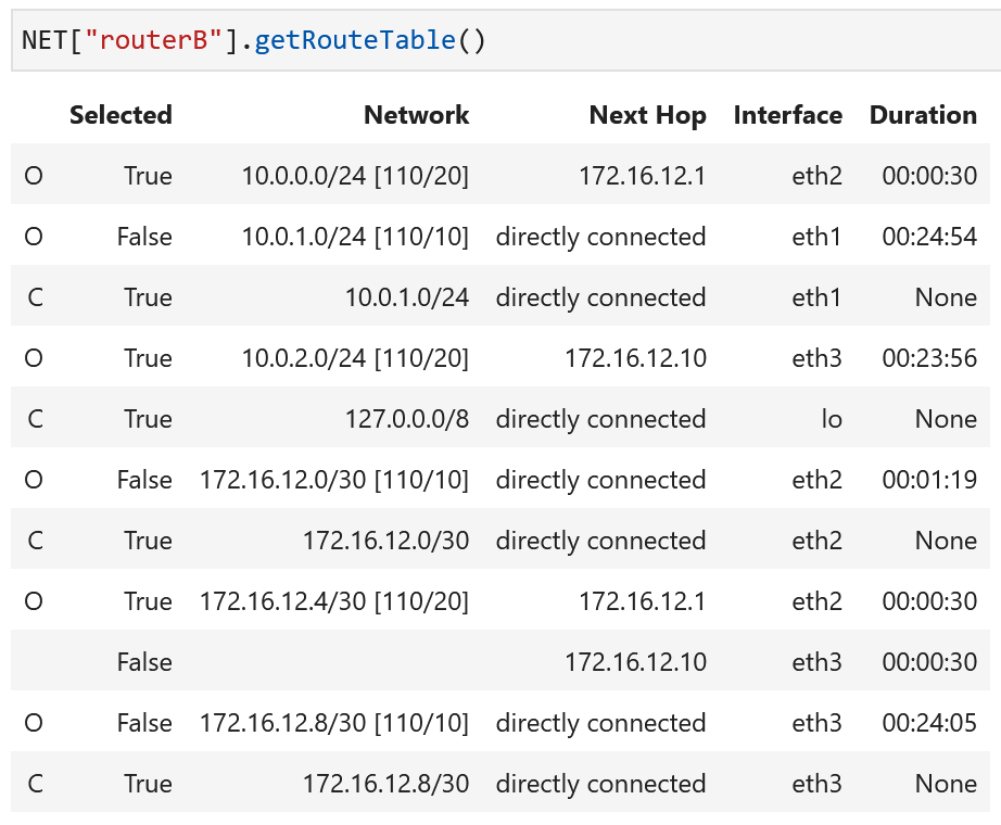
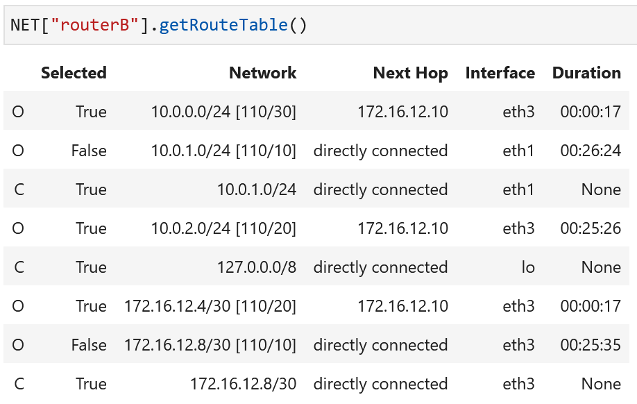
Retrieve the route tables at the routers to determine the path a packet may take on your topology.
Following the route to destination subnet 10.0.0.0/24 on routerB:
Verify the path of the packets from hostA to the destination subnet 10.0.1.0/24
by running traceroute:
In order to illustrate how routing protocols manage to utilize redundant links between routers,
disable a port on one of the routers. Observe, using the traceroute tool, how hosts can still
reach each other at L3.
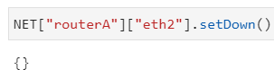
The command:
NET[<router-label>][<interface-label>].setDown()
in the lab notebook
sets the status of the interface eth2 to down for the router routerA.
Note
The interface can be brought back up using the command:
NET[<router-label>][<interface-label>].setUp()
The router labels in this topology are routerA, routerB and
routerC. The interface label examples are eth1, eth2, etc.
This is equivalent to a link failure in this network. Since there is redundancy for
that link through routerA to routerC
to routerB, the routing protocol will eventually
update the route accordingly.
Examine the route tables after this link failure scenario:
Verify the updated path that the packets follow after the port is set to down by running traceroute again:
Discussion Questions
Will a router forward a packet to the interface it has received it on?
What happens if there is a routing loop?
What are the implications of routers not considering the source IP address of a packet in routing decisions?
Learning Activities
Step 1
ssh into the hosts and examine the output of the traceroute command. Mark
down how many hops it takes for the hosts in the network to reach each other.
Step 2
Select a pair of hosts, run a traceroute from one host to the other. Save
the traceroute output for the first part your homework submission.
Step 3
Investigate how the routers update their selected routes when a link failure happens.
3a. Set the state of one of the ports of one of the routers to down to emulate a link failure scenario. Choose a port between the two routers traversed between the hosts you selected as part of Step 2 of the Learning Activities.
3b. Visually inspect the topology diagram based on the port that was set to down to determine what output may be expected for each traceroute request between the three hosts this time.
3c. Issue traceroute command on each host to the other two to observe the number
of hops it takes to reach each other this time.
Step 4
4a. Now, repeat the traceroute between the two hosts you selected in Step 2 of the Learning Activities.
Has the path between these hosts changed as a result of the altered router port state (the port down)?
4b. Copy the traceroute output from the traceroute run after the router port has been
disabled as instructed in Step 3 of the Learning Activities. Save this output for the second part of your
homework submission.
Step 5 – Homework
5a. Load the homework submission by running the following in the notebook:
%homework
5b. Copy the initial traceroute output from before you altered the router port state into the first
submission box (this is the output from Step 2 of the Learning Activities).
5c. Copy the traceroute output from after you altered the router port state into the second
submission box (this is the output from Step 4 of the Learning Activities).
5d. In the notebook, execute %homework to access the homework submission.
Paste each traceroute output into the appropriate entry field and press submit.
6. In your notebook, run:
%exercise
to solve the question(s) and submit this portion.
Lab Wrap-up
Please follow the instructions to delete your reserved topology and then close and halt your lab notebook and any open terminals on the lab service.