IP routes
How does a host send a packet to a destination in its subnet?
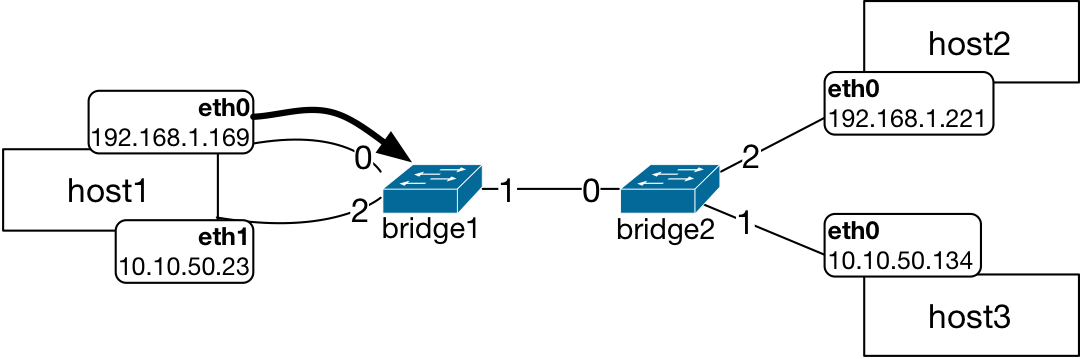
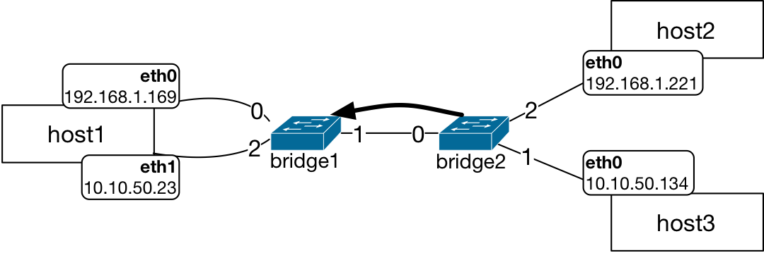
In this topology, host1 has two interfaces.

The host interfaces are on two different subnets, therefore, its route table has two entries.

Both subnets, 192.168.1.0/24 and 10.10.50.0/24, are reachable from host1.
host1 Route Table |
||
|---|---|---|
Destination Network |
Interface |
Gateway |
10.10.50.0/24 |
eth1 |
0.0.0.0 |
192.168.1.0/24 |
eth0 |
0.0.0.0 |
The host2 and host3 are on different subnets.
Their route tables have only one entry which is for their own subnet that they are
directly connected to: host2 is in the 192.168.1.0/24 subnet.
host2 Route Table |
||
|---|---|---|
Destination Network |
Interface |
Gateway |
192.168.1.0/24 |
eth0 |
0.0.0.0 |
host3 is in the 10.10.50.0/24 subnet.
host3 Route Table |
||
|---|---|---|
Destination Network |
Interface |
Gateway |
10.10.50.0/24 |
eth0 |
0.0.0.0 |
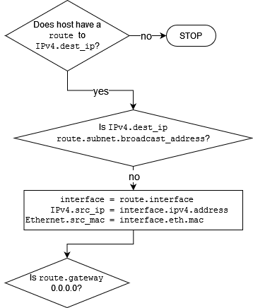
If a packet is sent from host1 to host2 - does host1 have a route to the destination IP address, 192.168.1.221?
There is a check point in the routing process flow for the route in the sending host route table.
Since host1 has a route to the subnet for host2 using its eth0 interface,
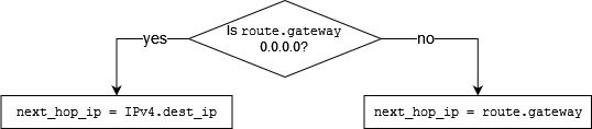
the next check in the logical flow is performed: does the route have a gateway?
The host1 is directly connected to the subnet of host2. Therefore, there is no
gateway. This is indicated by the gateway entry being 0.0.0.0 in the
route entry. When there is no gateway or, if the route.gateway is
0.0.0.0, the next_hop_ip is assigned to the destination IP address
of the packet, IPv4.dest_ip.
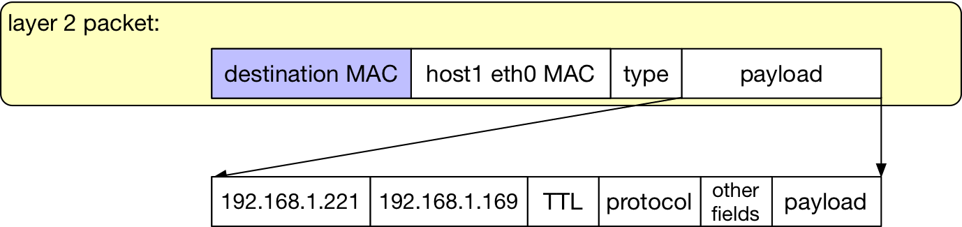
The next check is whether there is an ARP entry for the internal variable
in the flow, next_hop_ip, which is equal to the destination IP address,
192.168.1.221.
In essence, the host1 acquires the destination MAC address (that is, host2’s MAC address) in order to send this packet.
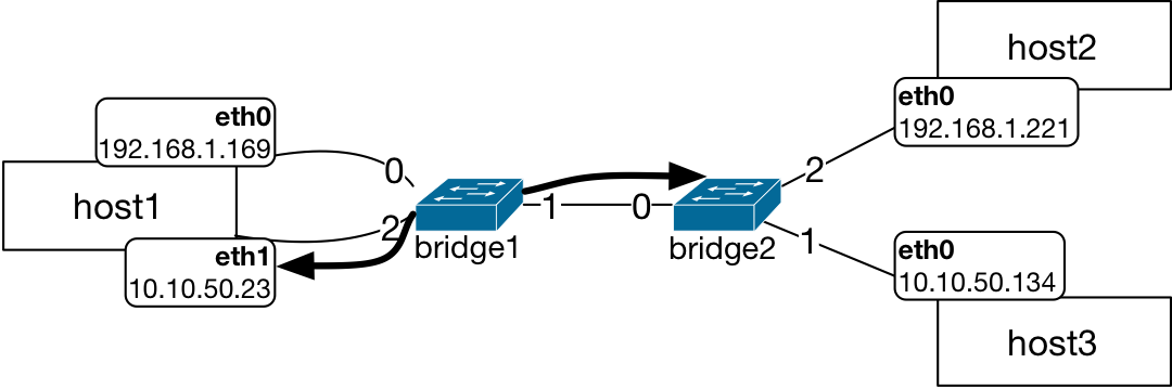
The ARP request message is sent by host1 at its eth0 interface.
The ARP request packet:
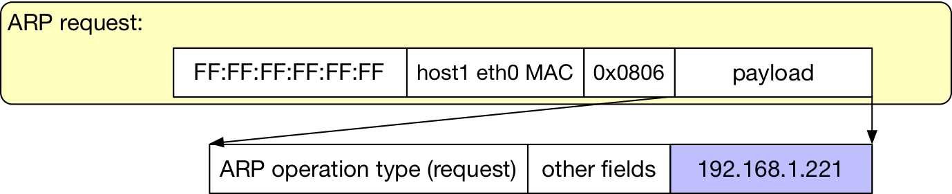
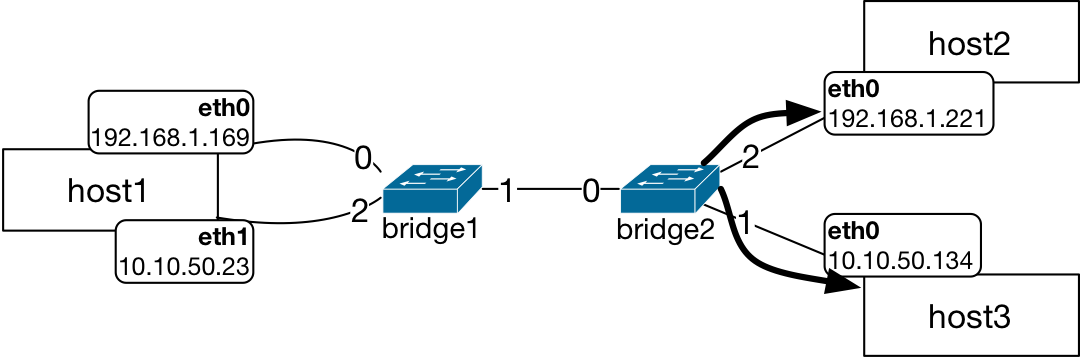
The broadcast packet is sent on all ports other than the incoming by the bridge1 and then by bridge2.
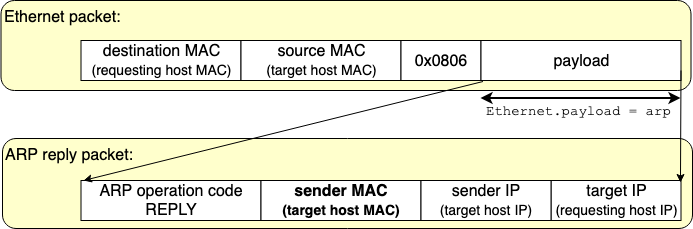
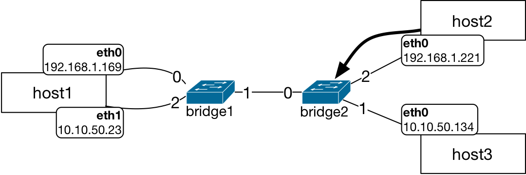
The host2 will send an ARP reply when it matches the IP address in the ARP request packet.
The reply packet will traverse the network back to host1 by being directly forwarded to the ports for host1 at bridges. Bridges will have an entry for host1 in their L2 table at this point.
The packet sent from host2 reaches bridge2 on port 2:
The bridge2 directly forwards this packet since it has already learned the MAC address of the host1 on its port 0:
Similarly, the bridge1 also directly forwards this packet since it has already learned the MAC address of the host1 also on its port 0:

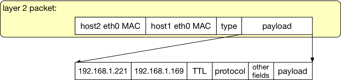
Now the host1 can send its packet to host2 using host2’s MAC address in the destination MAC address field of the Ethernet packet.
Tip
L1, L2, and L3 Network Topologies
This packet tracing example and the associated network topology was an example of how
the network topology is constrained by this time a layer 3 protocol, purely based on
subnet assignment. L1 topology is the physical wiring shown in the topology diagrams
above. L2 network topology in this case is the same as the L1. Bridges are not aware of
the L3 scoping of the forwarding and therefore, forward packets based on the MAC address
look up that they perform per Ethernet bridge behavior. However,
the network topology is partitioned into two distinct graphs in L3: One of them is
composed of host1, its eth0 interface, bridge1, bridge2, and finally the
host2. The other L3 topology graph is composed of host1, its eth1 interface,
bridge1, bridge2, and this time host3.
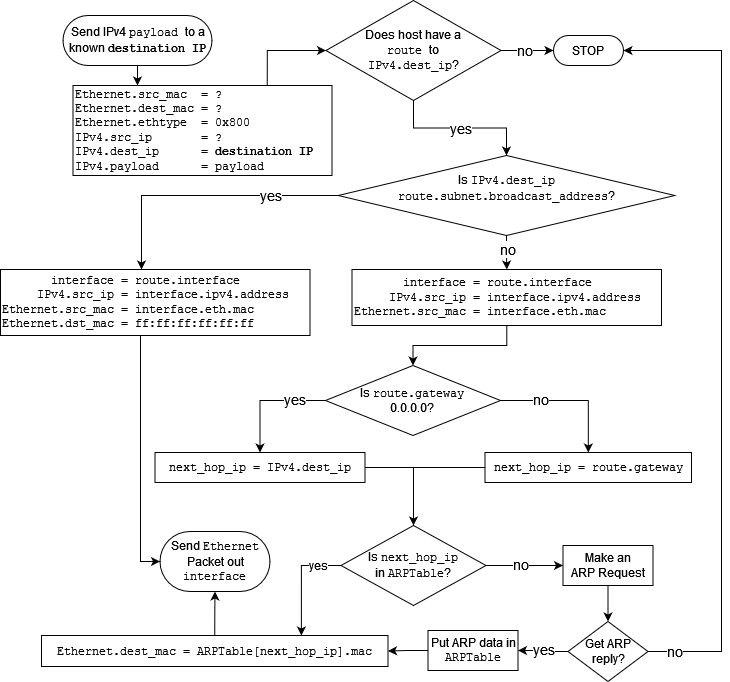
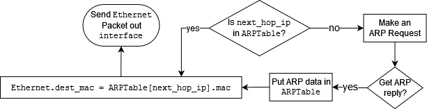
Route Lookup Process
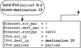
The routing process flow diagram is included below. Sending of an IP packet from a host for a given destination IP address involves checking destination IP address in the route table, checking the ARP table, and then preparing the packet’s L2 fields.