VLANs
A typical Ethernet network with devices that are of close proximity is usually referred to as a local area network. This definition is flexible on how the distance is measured. A local area network is the common term used to represent networks with physical boundaries such as a building’s networks, each floor in a building or a university or a high school campus. Usually local area networks are referred to as the abbreviated form, LAN.
Virtual LANs (VLANs) form logically isolated Ethernet networks within the same physical topology. This logical isolation allows for a virtual network within the physical network, hence the name virtual LAN. A tag header is added into the Ethernet packet to indicate that a packet exists in a named (tagged) broadcast domain, separate from packets in other broadcast domains. This allows L2 devices to make forwarding decisions that discriminate based on these tags.
Analogy: TV or Cable channels
When subscribing to a cable service, a household may be wired to receive a cable line from the service company. This single cable can deliver all channels available in the subscription agreement. All channels are sharing one cable through logical isolation achieved by their encoding schemes. The receiver needs to tune into one channel by decoding only that particular one.
Logical isolation can be achieved through frequency, encoding, and other methods over the same wire that may be carrying electromagnetic signals. In the case of the Ethernet, there is only one stream of packets being transmitted over any physical wire at any given time and per direction. Therefore, separation between VLANs is realized with a tag in the packet that indicates which VLAN broadcast domain the traffic flow belongs to.
VLAN-tagged Packets
VLANs are defined in the IEEE 802.1Q standard.
The packets that carry a VLAN tag have the Ethertype field set to 0x8100
to indicate that there is a tag header with 32 bits of information in the packet, along
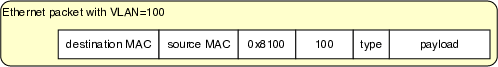
with the original Ethertype field. Below is an Ethernet packet with a VLAN header:
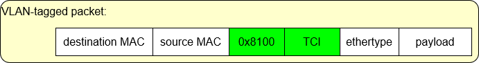
When a packet has a VLAN header, the original Ethertype field of the packet will
contain the value 0x8100. Consequently, the bridge will identify the VLAN header in the fields that
contain the 0x8100, and Ethertype will be understood as the 16 bits after the VLAN
header. If the original Ethertype is not equal to 0x8100, there is no VLAN to be
processed in the packet header.
This format ensures that all devices on the path of this packet are able to process the packet as Ethernet packets are processed generally, even if they do not understand VLAN headers.
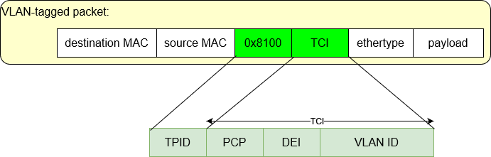
The tagged packet carries information about the VLAN protocol with the following fields:
TPID (16 bits): Tag protocol ID (value is shown as
0x8100)TCI (16 bits): Tag Control Information
PCP (3 bits): Priority Code Point
DEI (1 bit): Drop Eligible Indicator
VID (12 bits): VLAN ID
VLAN-aware Ethernet bridges (which includes all bridges in the lab environment)
perform MAC learning within the scope of the VLAN. In such bridges,
MAC addresses are added to the L2 table along with a VLAN ID.
In the bridge L2 table, the column VLAN displays the VLAN ID in which
a MAC address is learned.
Port |
VLAN |
MAC |
Age |
|---|---|---|---|
2 |
18 |
aa:aa:bb:bb:13:9f |
48 |
5 |
528 |
28:39:10:82:13:9f |
19 |
Forwarding When Hosts Tag All Packets
Isolated topologies can be achieved by enabling the host endpoints to send tagged packets to indicate their membership of specific logical networks. In essence, the tag then is an extension of the existing host endpoint identifier (the interface MAC address) from the perspective of the Ethernet bridges. When hosts send tagged packets, the adjacent bridge would keep all forwarding traffic within its corresponding VLAN by creating L2 table entries associated with each VLAN. MAC learning and the forwarding decisions would be made within the VLAN.
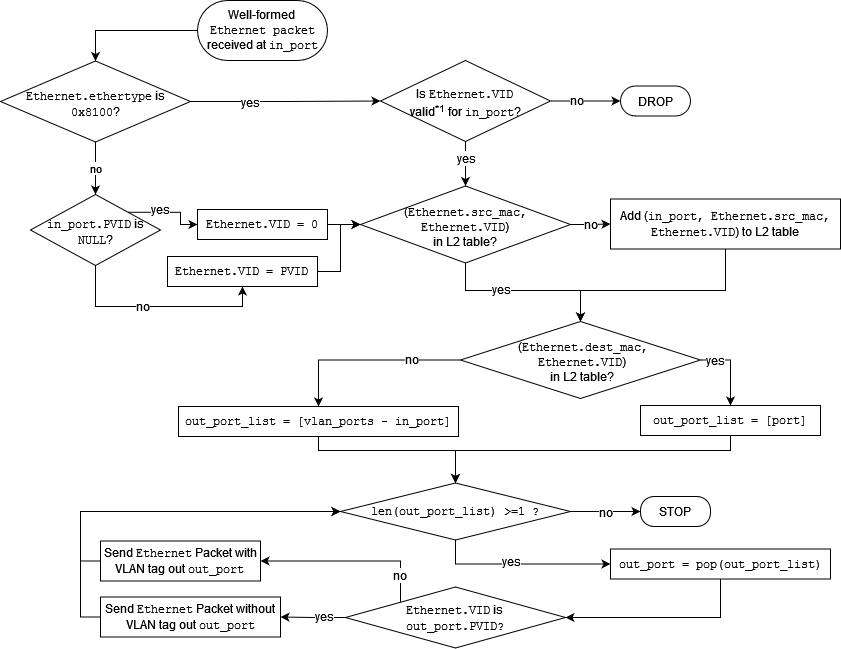
There is a modified process flow chart for the bridge forwarding and MAC learning when hosts are always sending tagged packets:
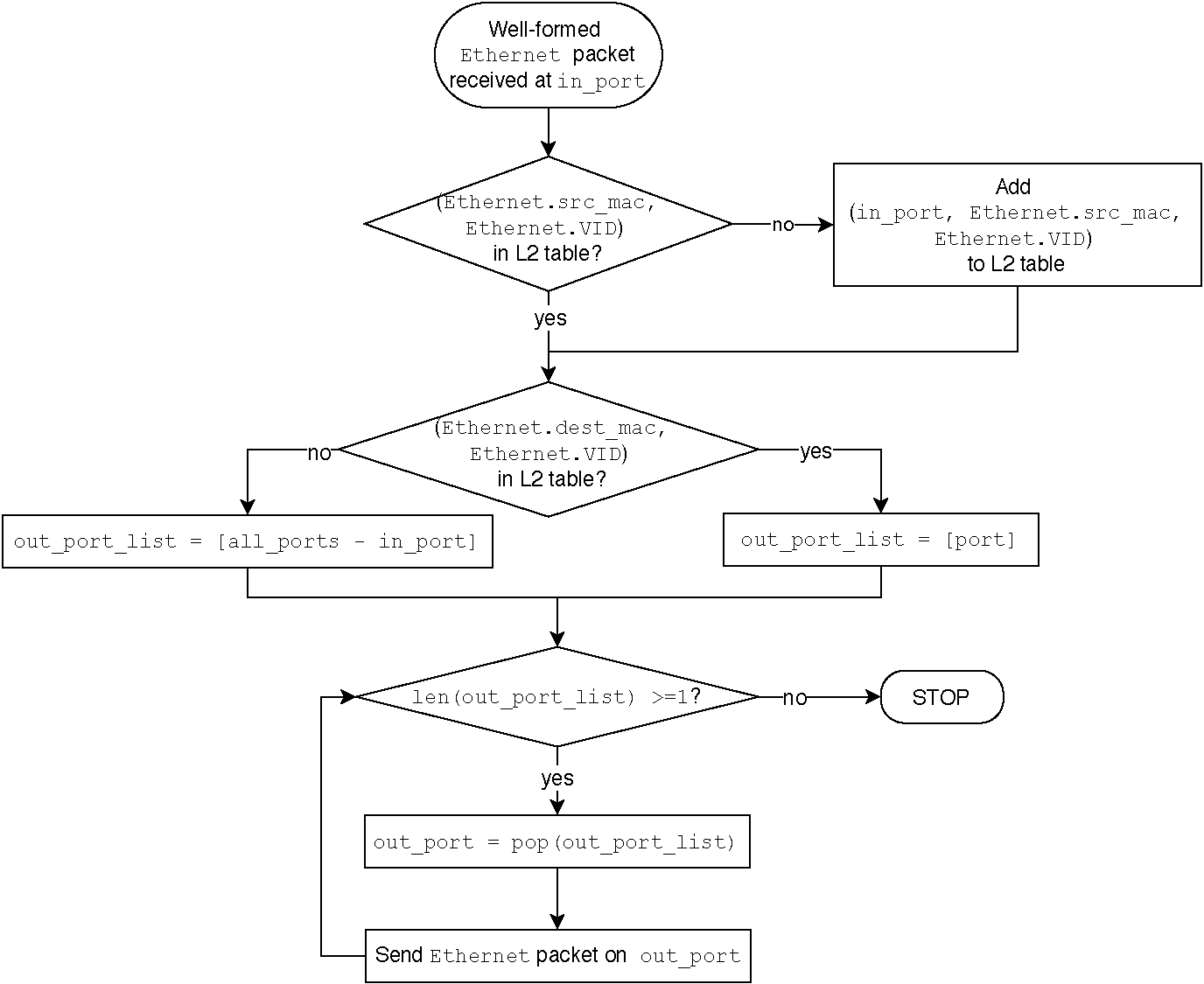
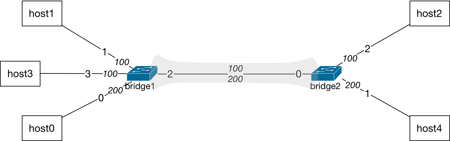
With no configuration changes on the bridges, the identifier in the packets is now a tuple (MAC address, VLAN) that the bridge uses to perform MAC learning and forwarding decisions. For example, in a topology where VLANs are assigned to the interfaces of hosts, as shown below, hosts are always sending tagged packets that indicate which broadcast domain their packets belong to.
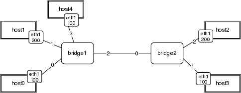
The hosts with an interface configured to be in VLAN-100 will be sending packets with a tag of value 100:
Similarly, the VLAN-200 hosts will send packets with tag value of 200:

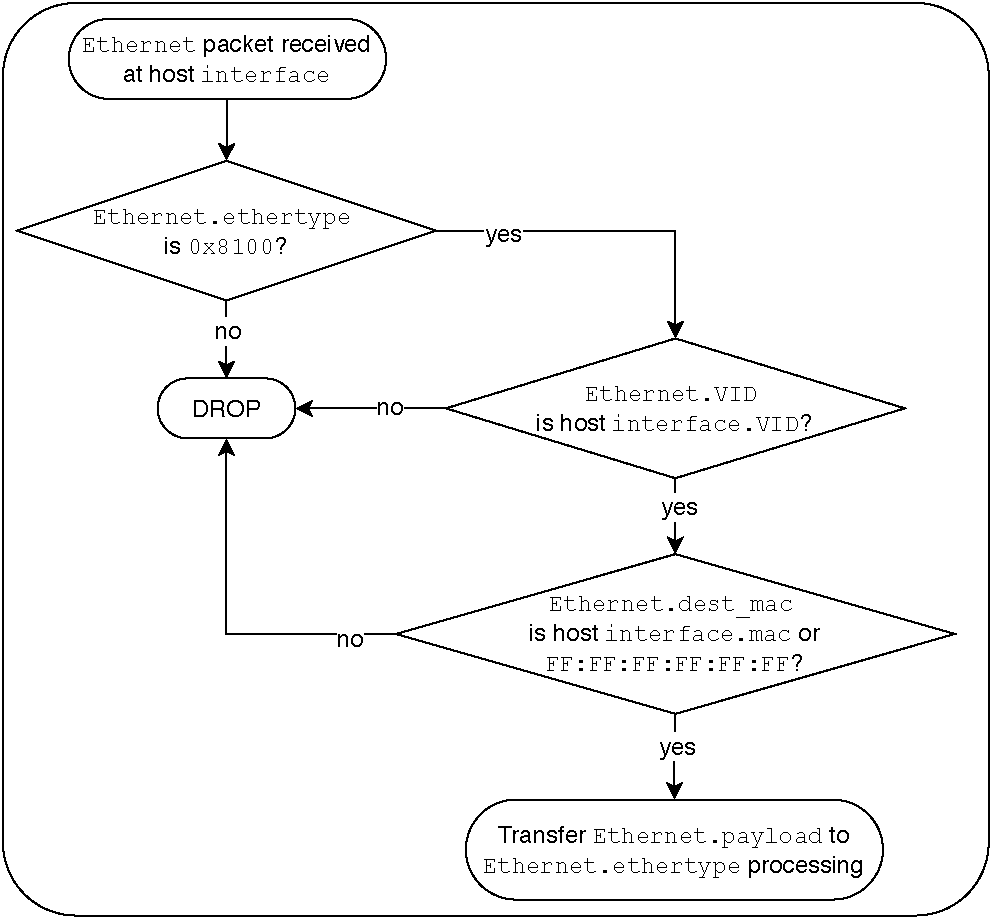
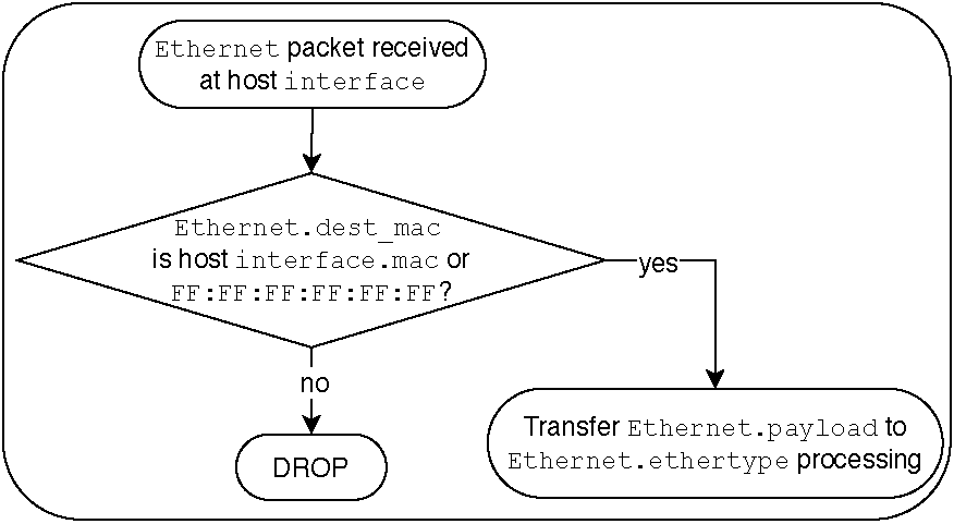
The hosts process incoming packets with an additional step that always verifies the tag to make sure they are communicating within the logical network created through the tags. In this respect, the process flow chart for host interfaces receiving packets is shown below.
VLAN Port Configurations
Bridges have the following port configuration options:
A port VLAN (PVID) may be set - this port is then referred to as
access
The PVID may also be referred to as the
nativeVLAN IDPackets will be forwarded on this port without tags
Or a port can have no PVID set - this port is then referred to as
trunk
This port will accept packets in any VLAN (or no VLAN)
Packets will be forwarded with tags (or not) based on the flow chart
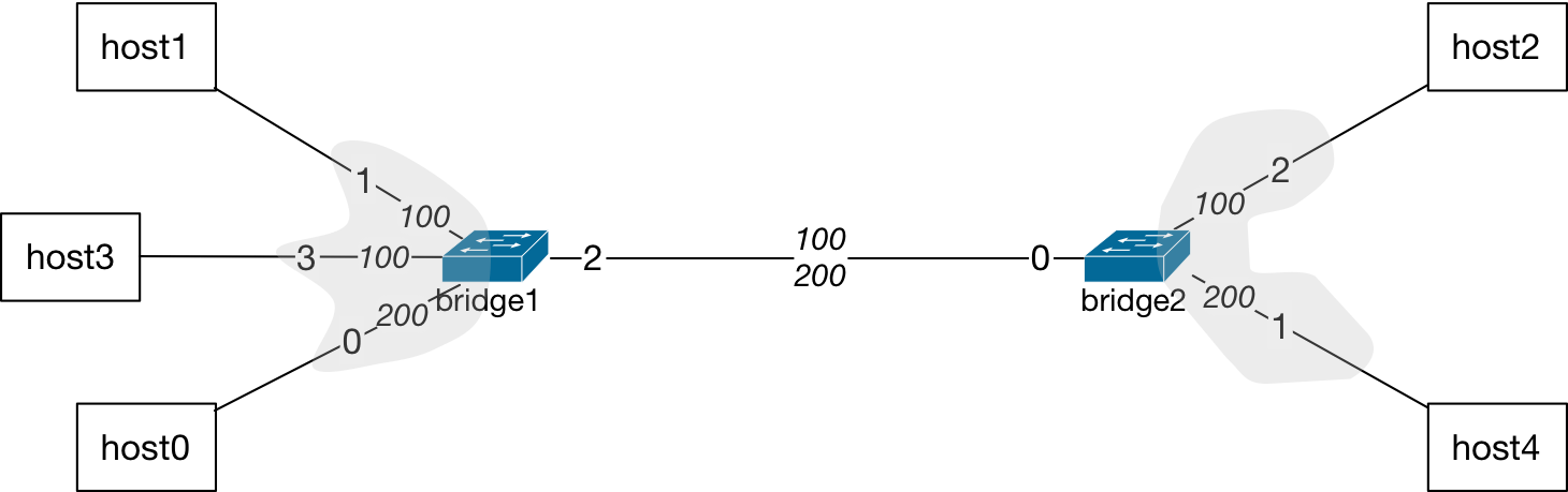
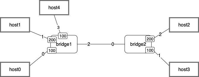
Here is an example topology where bridge1 and bridge2 have port VLAN
configurations that are displayed in the table below:
|
||
|---|---|---|
Port |
Type |
Native |
0 |
Access |
200 |
1 |
Access |
100 |
2 |
Trunk |
None |
3 |
Access |
100 |
|
||
|---|---|---|
Port |
Type |
Native |
0 |
Trunk |
None |
1 |
Access |
200 |
2 |
Access |
100 |
Trunk ports usually are for links between two bridges that carry multiple VLANs across different L2 networks.
Tip
Usage Insight
An Ethernet bridge may have many ports such as 48 or more. Typically, any host connecting to such a bridge has to be within a short distance away, such as the closet in a building floor that has all of the network equipment. The cabling then enables wall jacks to connect office computers to the network.
If a department in an organization has offices and personnel with computer access to resources on multiple floors of the same building or across different buildings in a campus, all members of the department may require to be on the same network to access resources with similar privileges. Therefore, network administrator may configure bridges to connect each other with a VLAN assignment for that particular department to consolidate their resource access.
In addition to resource access scenarios, VLANs may be utilized to isolate and manage traffic in networks so that new traffic demands or any fluctuations in load may be re-directed.
Ethernet Bridge MAC Learning with VLANs
The flow chart for the MAC learning is expanded to include specific actions taken by Ethernet bridges when port VLANs may be configured.
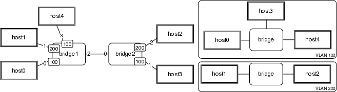
Packet forwarding process in an Ethernet bridge with port VLAN configurations.
With port configuration at the bridges, the same topology will not need tagging of the packets at host endpoints. The bridges will separate the broadcast domains through the port configurations.
Now, this topology can be regarded as if there are two separate bridges that forward the traffic and there is no path between the two VLANs configured at the bridge devices.
The hosts are not generally aware of the VLAN configurations at the bridges. Their Ethernet packet processing is simplified:
Modified MAC Learning Flow Chart for Ethernet Bridges
There are three main stages of Ethernet bridge packet forwarding:
MAC learning
Forwarding decision making
Forwarding of the packet
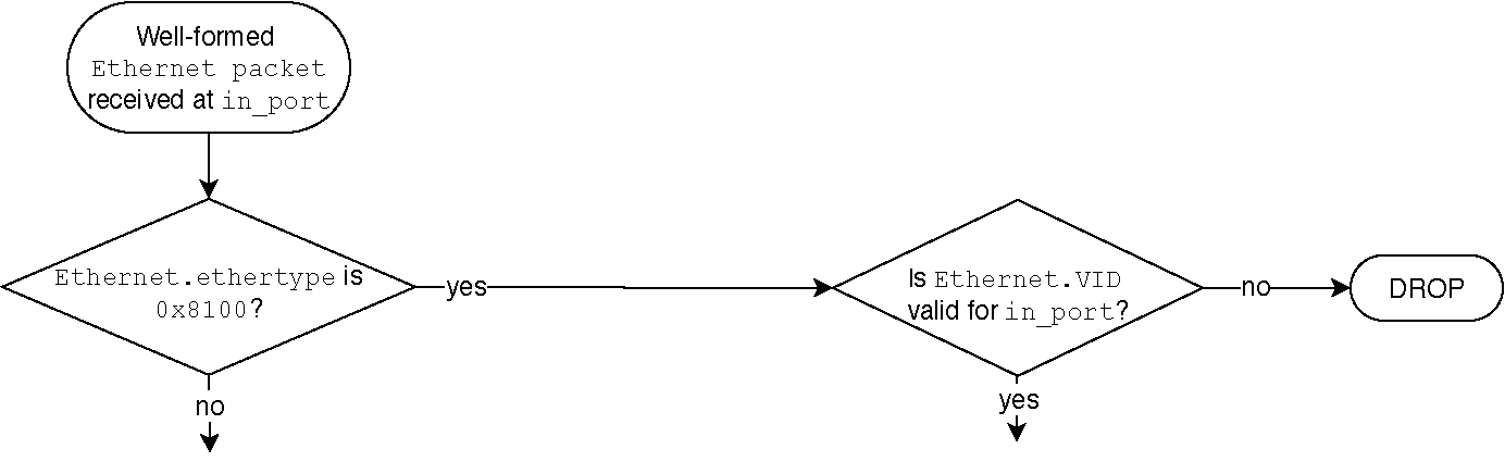
The modified flow chart includes a pre-processing of incoming packets based
on the presence of a VLAN tag in the packet. If the packet arrives with a
tag, the Ethertype is 0x8100. The packet’s tag is then checked to see
whether it is valid for the incoming port. This decision results in a
yes if a tagged packet is accepted at this port and the tag is valid.
Otherwise, the packet is dropped.
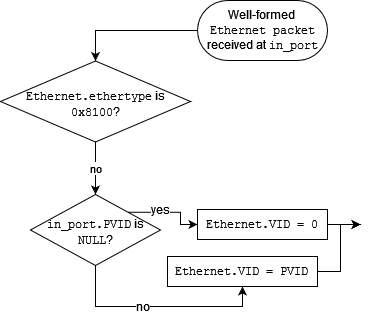
If the packet arrives with no tag, the pre-processing of the packet results
in a tag being added to it before the main three stages of the packet
processing. In this manner, the bridge has a uniform processing of the
packet within a VLAN broadcast domain. An untagged packet has to be accepted
at the input port, which is another configuration item in various
vendor implementations of VLAN support in bridges. Next, the PVID
configuration of the incoming port is checked. If there is no PVID
configuration, the in_port.PVID is NULL. In this case, the bridge
adds a tag of value zero to the packet. If there is a PVID configured
for the incoming port, then the packet is added a tag value equal to the
port VLAN ID. At this stage, the packet is now tagged internally by
the bridge. The next stage, MAC learning, starts with this tagged packet.
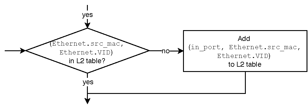
The bridge then performs a lookup in its L2 table for the pair,
(Ethernet.src_mac, Ethernet.VID). If this value is not in the table,
it is added in. Otherwise, next stage takes place where a forwarding
decision is made.
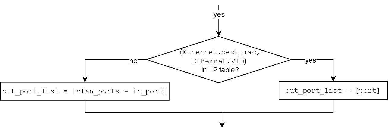
During the decision making for forwarding of the packet, the bridge
performs a lookup of the packet’s destination MAC address in its L2
table scoped by the VLAN tag. Essentially, the pair
(Ethernet.dst_mac, Ethernet.VID) is looked up in the L2 table. If
exists, the output port is identified in the row entry with that pair.
Otherwise, the bridge determines all vlan_ports which is all ports
with the same PVID along with ports that have no port VLAN configuration.
The out_port_list is composed at this stage by subtracting the
in_port from the vlan_ports list.
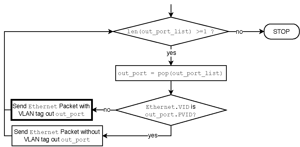
During the final stage, the bridge forwards the packet to the
ports determined in the decision making stage, to the ports in the
out_port_list. This stage is where the already tagged packet is
either forwarded out with a tag or the tag is stripped off before the
forwarding. The packet is sent out after stripping off the tag if
the outgoing port has a port VLAN ID that is equal to the tag.
Otherwise, the tag is left intact.