Spanning Tree Protocol
The spanning tree protocol (STP) was invented by Radia Perlman in 1984 to
prevent bridges from forwarding in a looped topology. That is, the protocol shuts
down strategic ports even if they are physically wired to prune edges on
looped paths. STP changes the state of bridge ports
to prevent forwarding of packets in an infinite circulation within the network.
Bridges would then utilize only the forwarding ports while other ports are in a
blocked state.
A network graph overview is included here to continue to use graph representation of network topologies.
Network Graph
In the context of computer networks, analysis tasks are possible with the tools and methods available to operate on a graph. In this respect, representation of network topologies as a graph to solve computer networking problems is a common practice. Therefore, this section is a brief introduction to the terminology, methods, and tools associated with graphs.
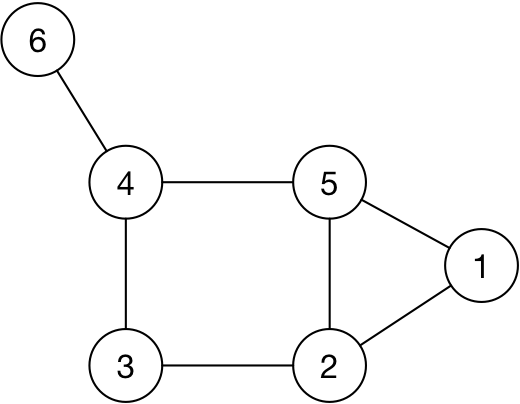
A network graph is a collection of edges and vertices. For example, the vertices and the edges for the graph in the picture are:
V = {1, 2, 3, 4, 5, 6}
E = {{1, 2}, {1, 5}, {2, 3}, {3, 4}, {4, 5}, {4. 6}}
Subgraph
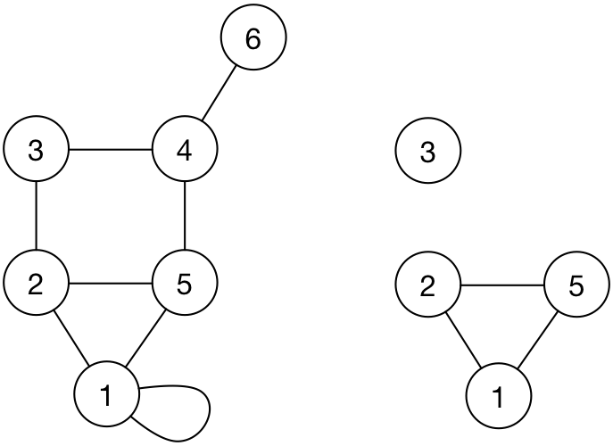
A subgraph can be formed from any set of edges and vertices of a given graph.
Note
Subgraph of a graph is useful when talking about what logical connectivity may be achieved on an existing physical connectivity. In essence, a subgraph of the physical connectivity graph will be used to represent what a protocol may be enabling as logical connectivity.
Connectivity
The subgraph of a graph is called connected if all vertices of the original graph are reachable from each other. For example, the illustration shows a connected subgraph and another subgraph that is not connected for the same original graph.
Connectivity is sometimes referred to as reachability which will indicate specific protocol communications being possible between two given end hosts, referring to the logical connectivity. For example, the physical wiring of a network as a graph may be connected, that is, there may be a cable (or a set of cables and network devices) between any two vertices. Yet, the nodes maybe not have logical connectivity in a specified protocol due to the way that protocol was configured at the nodes.
Tree and Spanning Tree
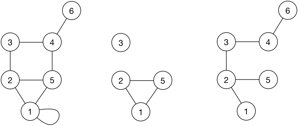
A subgraph with no cycles (no loops) and connected constitutes a tree topology. That is, any vertex is reachable from any other within the subgraph through a single path.
Attention
A spanning tree subgraph has all of the existing vertices of the original graph.
Example spanning tree subgraphs of the following graph is included here.
STP Protocol and Algorithm
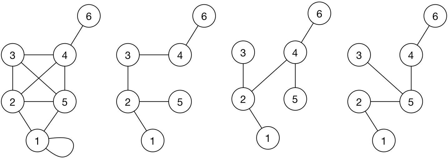
A network graph with loops can have multiple spanning tree (ST) subgraphs.
Creation of an appropriate ST subgraph is realized through a communication
protocol that runs between the bridges, the spanning tree protocol (STP).
Bridges exchange messages to determine the existing topology state,
namely, determination of immediate neighbors. Based on bridge identifiers,
port numbers, and configuration preference of the network administrator,
a root bridge is picked among the bridges. The ports within the tree
subgraph are set to forwarding state while others to
blocking state for packets to flow only within the subgraph. When
in the blocking state, the port does not listen to or forward packets.
However, its administrative state is still up (enabled).
If a port is blocking and connected to a port that is forwarding
on the shared link between two bridges, packets will be forwarded by
the bridge with the forwarding port to the blocking port. The
blocking port will receive and ignore these packets and no action
will be taken by the bridge on those data packets.
Bridges use the reserved MAC address, 01:80:c2:00:00:00, as the
destination MAC address in their STP messages. These packets are called
link local.
Important
Bridge STP packets are not forwarded beyond the receiving
node. When a bridge receives a packet that is destined to the reserved
MAC address for STP, 01:80:c2:00:00:00, the packet is processed by
the STP process and never forwarded to any of its neighbors.
Also note that all bridge ports continuously send STP packets regardless
of their STP port status, forwarding or blocking. The STP port
status applies to data packets that are received or forwarded on a
bridge. The bridge identifies data packets with their destination MAC
addresses (not equal to 01:80:c2:00:00:00).
Bridges keep sending STP hello messages on all ports to indicate which
links are up. When there is a link failure on a forwarding bridge
port, a blocking port may be converted to the forwarding state to
maintain the reachability in the network. STP handles such failure modes
by providing messaging mechanisms to update individual existing
topology knowledge and converge from the failure state to a new spanning
tree graph topology state.
Attention
Since all ports of the bridges run STP, hosts will receive STP packets from
the bridges. This is the main reason to filter out the destination MAC address
01:80:c2:00:00:00 when running the tcpdump command on hosts
in lab experiment topologies. The periodic STP packets keep
bridges informed of any failures, new bridge additions, and other
port changes.
Root Bridge
Bridges will end up electing one bridge as the root bridge. All ports of
the root bridge will be in forwarding state. There is only one path
from any of the endpoints to any other in the topology since this is a
tree graph.
The root bridge selection and the spanning tree subgraph formation are processes that utilize a number of parameters from the bridges. All parameters and the processes can be configured to converge on a particular spanning tree subgraph of the original network, thereby setting the root bridge.
Failover Scenario
Since bridges send hello STP packets on all of their ports, a link
failure due to any port of a bridge will be detected quickly. This
change in network state will trigger a recalculation of the spanning tree and
the root bridge. The emerging new spanning tree may convert some of the previously
blocking ports into forwarding ports.
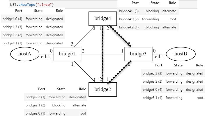
Spanning Tree before a Link Failure
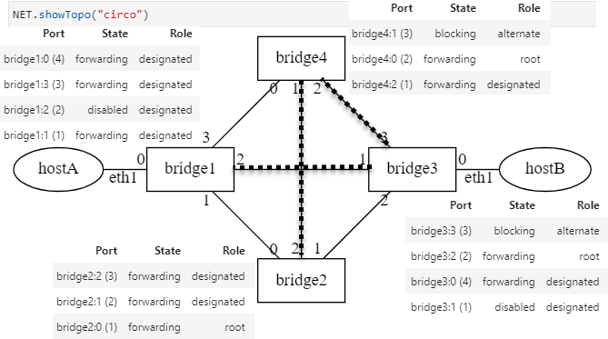
Spanning Tree after a Link Failure
See also
Further Reading List
Interconnections, Second Edition: Bridges, Routers, Switches, and Internetworking Protocols by Radia Perlman, Addison- Wesley, Reading, Mass., 1999, ISBN 0- 201-63448-1.