Routers
For a given topology with multiple router hops, packet forwarding processes will take place at L2 and L3.

The set of network interfaces in a subnet can be shown with a subnet cloud that represents the network interfaces for the IP address range. In this fashion, it is easier to identify where routing is taking place since each subnet interfacing with another one has a router at the connecting point of the clouds.
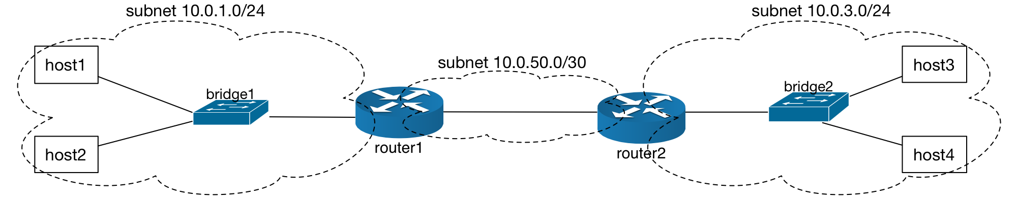
In this topology, host1 and host2 are in the 10.0.1.0/24 subnet along with one
interface of router1, and similarly, host3 and host4 are in the 10.0.3.0/24 with
an interface on router2. The router1 and router2 interfaces are in the
10.0.50.0/30 subnet.
Trace Packet Forwarding
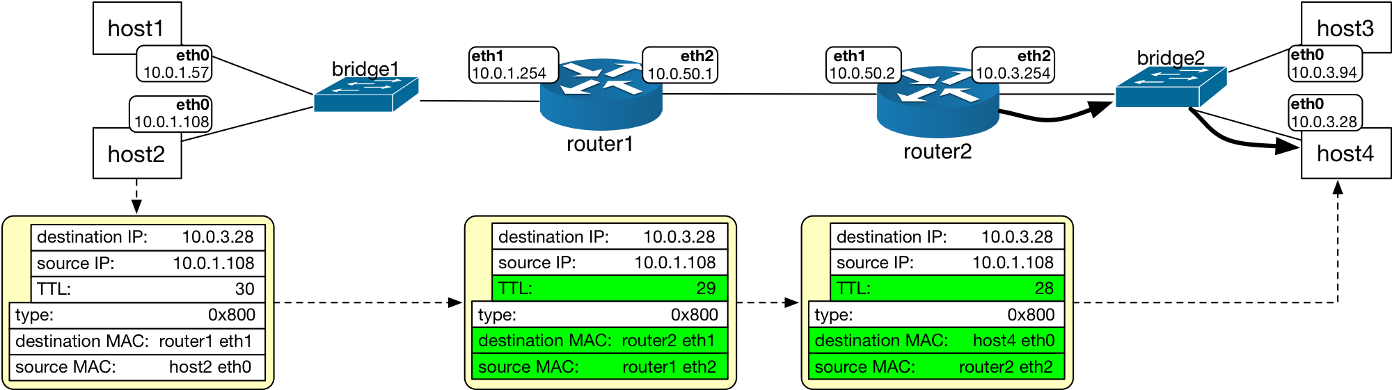
Let’s trace packet forwarding behavior in this network topology while also examining the entries in the respective route and ARP tables. Assumptions:
Both bridges have learned interface MAC addresses that they are connected to
Router ARP tables already contain the MAC addresses for interfaces in directly connected broadcast domains
Hosts have ARP entries for the nexthop IP of each of their routes with gateways
Host Route and ARP Tables
Host route tables include their subnet as directly connected (no gateway) in addition to the route to the subnet where the other hosts reside on the other side of the router:
host1/host2 Route Table |
||
|---|---|---|
Destination Subnet |
Interface |
Gateway (Nexthop IP) |
10.0.1.0/24 |
eth0 |
|
10.0.3.0/24 |
eth0 |
10.0.1.254 |
host3/host4 Route Table |
||
|---|---|---|
Destination Subnet |
Interface |
Gateway (Nexthop IP) |
10.0.3.0/24 |
eth0 |
|
10.0.1.0/24 |
eth0 |
10.0.3.254 |
Since we assumed gateway MAC address exists in the host ARP tables:
host1/host2 ARP Table |
||
|---|---|---|
MAC |
IP |
Expiration Time |
router1 eth1 |
10.0.1.254 |
T |
host3/host4 ARP Table |
||
|---|---|---|
MAC |
IP |
Expiration Time |
router2 eth2 |
10.0.3.254 |
T |
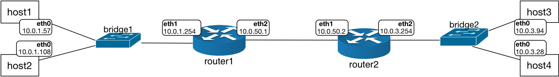
At the Router: Route and ARP Tables
Each router will also have their respective route tables that list
all subnets they are directly attached to in addition to the subnets
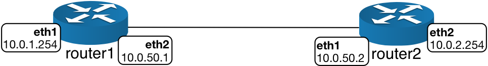
that are reachable through a gateway. The router-to-router link has
its own subnet since those interfaces should be able to forward traffic
to each other, 10.0.50.0/30, which is an IP address range that is composed of
two host IP addresses: 10.0.50.1 and 10.0.50.2.
Route table for router1:
router1 Route Table |
||
|---|---|---|
Destination Subnet |
Interface |
Gateway (Nexthop IP) |
10.0.1.0/24 |
eth1 |
directly attached |
10.0.3.0/24 |
eth2 |
10.0.50.2 |
10.0.50.0/30 |
eth2 |
directly attached |
Route table for router2:
router2 Route Table |
||
|---|---|---|
Destination Subnet |
Interface |
Gateway (Nexthop IP) |
10.0.1.0/24 |
eth1 |
10.0.50.1 |
10.0.3.0/24 |
eth2 |
directly attached |
10.0.50.0/30 |
eth1 |
directly attached |
Since we had assumed all MAC addresses are known by the end hosts and routers, the ARP tables for the routers are also fully populated with the relevant entries:
ARP table for router1:
router1 ARP Table |
||
|---|---|---|
MAC |
IP |
Expiration Time |
host1 eth0 |
10.0.1.57 |
T1 |
host2 eth0 |
10.0.1.108 |
T2 |
router2 eth1 |
10.0.50.2 |
T3 |
ARP table for router2:
router2 ARP Table |
||
|---|---|---|
MAC |
IP |
Expiration Time |
host3 eth0 |
10.0.1.57 |
T1 |
host4 eth0 |
10.0.1.108 |
T2 |
router1 eth2 |
10.0.50.1 |
T3 |
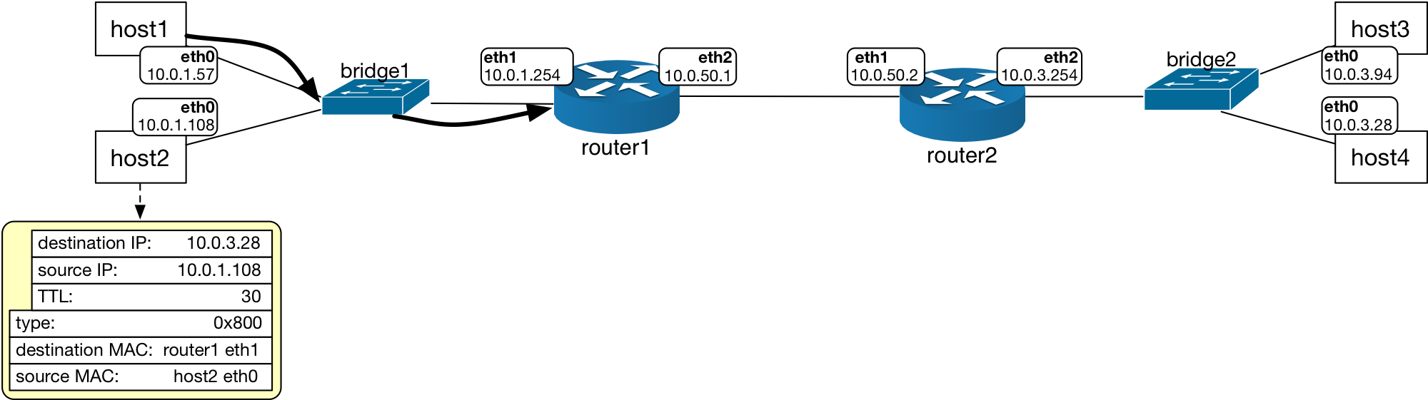
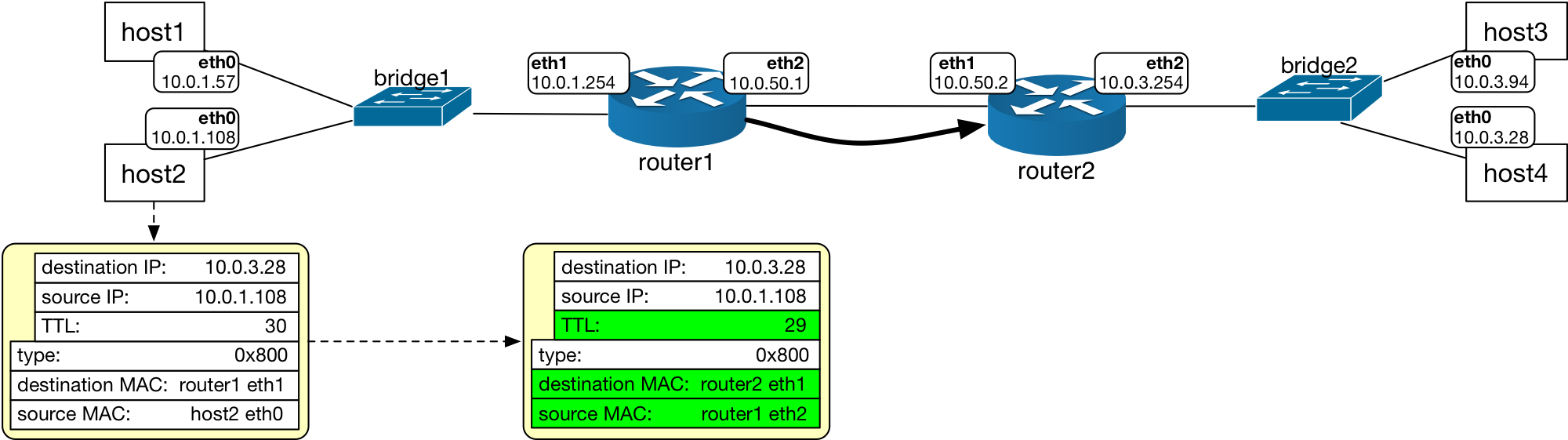
Given the ARP and route tables, the packet from host2 to host4 will be forwarded in the following manner.
Misconfiguration of Routes: L3 Loop
At L2, bridges run the Spanning Tree Protocol to prevent packets from recirculating in the network forever and multiplying through broadcasts. Looped L2 topologies result in problematic situations for the networks because the principles of the Ethernet bridge behavior:
Packets are forwarded without tracking the number of times they have visited a bridge
Packets are broadcast on all but incoming port (flood) when there is no match in the L2 table
Routers on the other hand, decrement the IP packet header field value called the TTL (time to live) so a packet traverses the network through a limited number of routers. Packets are forwarded towards their destination using the information in route tables: no route for a destination IP address (subnet) would result in dropping of the packet as opposed to the behavior of bridges where forwarding is an automatic flood when the destination MAC address look up does not return a match.
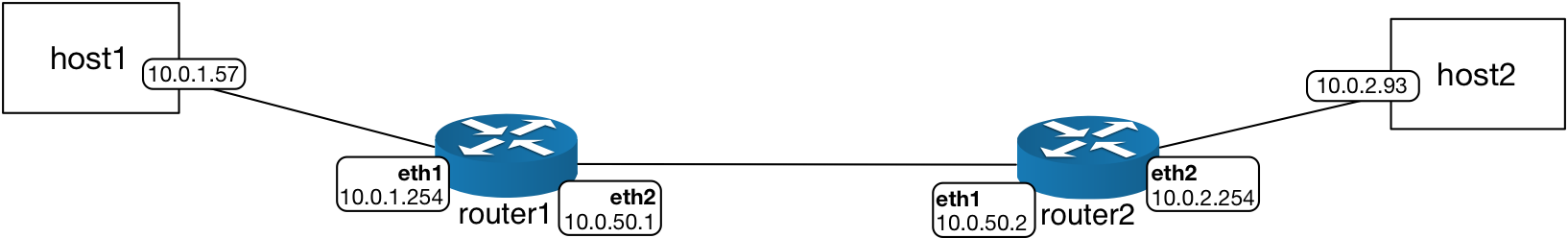
Given the topology with two routers and the following route tables at routers, packets would traverse this network in a loop between the routers, resulting in the eventual expiration of the TTL.
The example topology and IP address assignments to illustrate a route misconfiguration resulting in packets recirculating between the two routers.
Route table for the router1 has a subnet entry that is not shown in the
network topology diagram, the subnet 10.0.5.0/24 has a route on
interface eth2 with the nexthop IP indicated as the interface IP
address of router2.
router1 Route Table |
||
|---|---|---|
Destination Subnet |
Interface |
Gateway (Nexthop IP) |
10.0.1.0/24 |
eth1 |
directly attached |
10.0.2.0/24 |
eth2 |
10.0.50.2 |
10.0.5.0/24 |
eth2 |
10.0.50.2 |
10.0.50.0/30 |
eth2 |
directly attached |
Route table for the router2 has a subnet entry that is not shown in the
network topology diagram, the subnet 10.0.5.0/24 has a route on
interface eth1 with the nexthop IP as the interface IP address at router1,
effectively creating a loop in L3, due to a misconfiguration of the routers.
router2 Route Table |
||
|---|---|---|
Destination Subnet |
Interface |
Gateway (Nexthop IP) |
10.0.1.0/24 |
eth1 |
10.0.50.1 |
10.0.2.0/24 |
eth2 |
directly attached |
10.0.5.0/24 |
eth1 |
10.0.50.1 |
10.0.50.0/30 |
eth1 |
directly attached |
The route for the destination subnet 10.0.5.0/24 is listed with the other router
interface IP as the nexthop IP address.
For a packet that is sent to the 10.0.5.0/24 subnet, this route configuration will result
in the packet being transmitted between the routers over and over again.
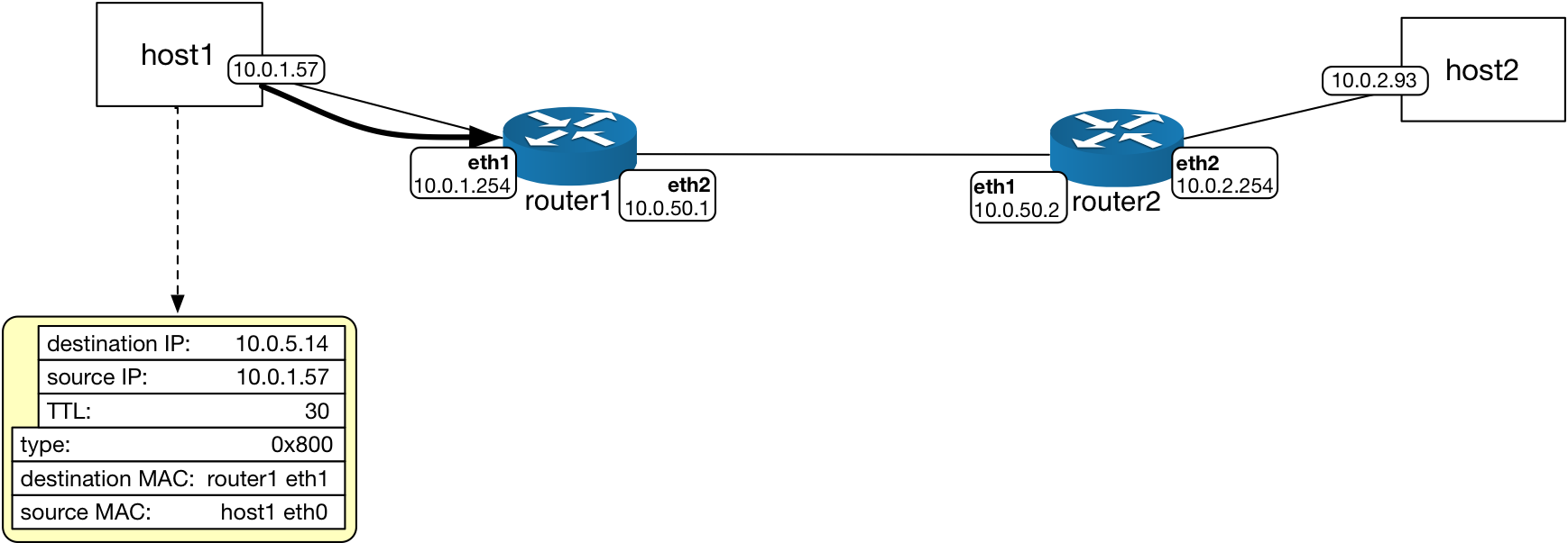
The host1 sends the packet with TTL set to 30 and destination MAC address is the router1
eth1 interface.
The router forwards per its route:
Destination subnet:
10.0.5.0/24Interface:
eth2Nexthop IP:
10.0.50.2
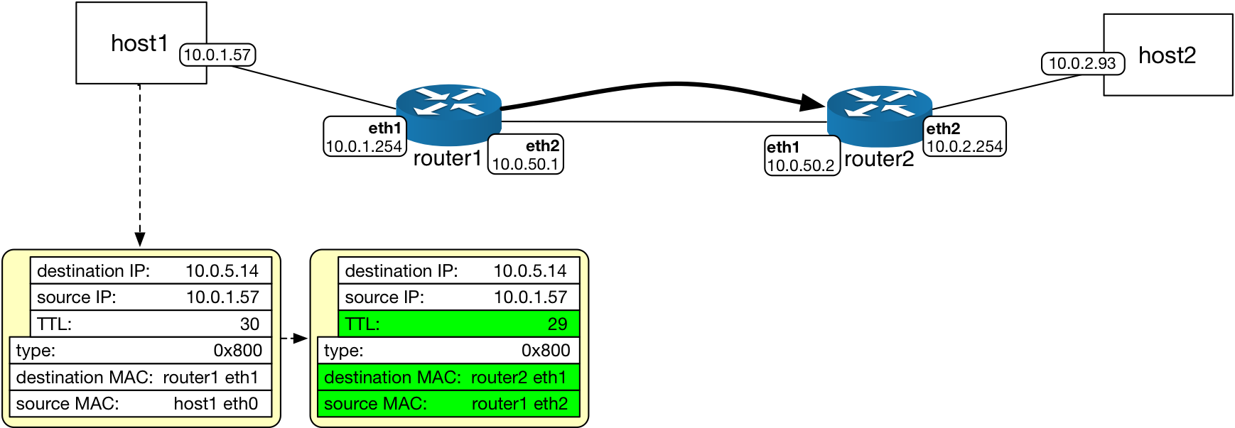
The router1 decrements the TTL before forwarding the packet to router2 network
interface eth1.
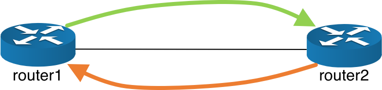
In this fashion, the packet gets forwarded back and forth between the routers:
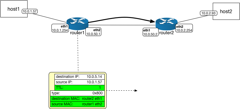
Before TTL expires, the packet will be forwarded from router1 to router2 with the
TTL field equal to 1.
Once router2 receives this packet and looks up the destination IP address in
its route table, it will forward it back to router1 but decrementing the
TTL will eventually make the TTL equal to zero and the packet will instead be
dropped. An ICMP control message will be sent back to the source with a type
code for TTL expired to indicate that packet could not be delivered and the
TTL has expired.
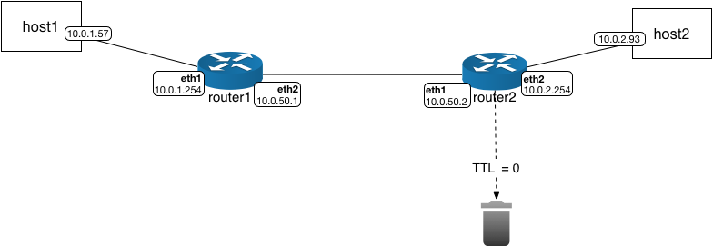
Once TTL expires, the packet will be dropped.