Lab - 6: VLANs
Objectives
The lab is on observations of:
Ethernet bridge with a VLAN configuration
VLAN scoping of packets
Reconfiguration of PVID value
Load Lab Network
Execute the commands to build your lab network:
%load_ext uhed
%lab
In order to conduct this lab, please pick VLANs lab from the dropdown menu and click on the Build Network button. Once successfully built, display the network topology using:
NET.showTopo()
Open a terminal using the
Use File  New Terminal
in the top menu and then
ssh (secure shell) into the hosts using the command:
gssh <username> <devicename>
Note
Reminder Example on ssh
For example, for a user name, student01, ssh
into the host1 using the command gssh student01 host1 at the terminal.
Topology Orientation
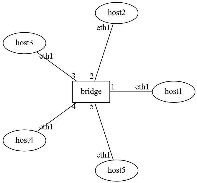
Lab Network Topology: There are five hosts. Ports of the bridge have a VLAN ID configured.
Observation Guideline
In order to make observations, the environment displayed in the diagram must be prepared.
Determine the initial state of the network that has been built, including IP and MAC addresses of the hosts:
NET.showInterfaces()
On the lab notebook, execute:
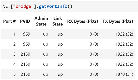
NET[<bridge-label>].getPortInfo()
to retrieve the current VLAN configuration of ports. The port configurations are displayed in a table for the bridge in the topology, as shown in the screenshot below.
Open a terminal for each of the hosts (two terminals will be needed for hosts where packets are being sent and captured). The figure below shows where terminals will be needed on hosts.
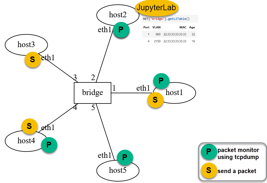
The environment includes terminals where packets are sent within a VLAN while observing the packet’s presence or absence at other hosts. All flooding will happen at the ports that are members of the VLAN.
Bridge L2 Table: VLAN Scoping
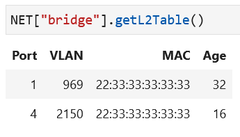
The bridge has an empty L2 table at the beginning of the experiment since no host has sent a packet in this network yet.
The L2 table has the columns: port number, VLAN tag, MAC address, and age time. A new row is added each time a new MAC address is encountered in the source MAC field of an incoming packet. The current bridge layer2 table can be retrieved in the notebook:
NET[<bridge-label>].getL2Table()
Bridge Port VLAN (PVID) Configuration
The bridge VLAN port configuration can be retrieved using the following command in the lab notebook:
NET[<bridge-label>].getPortInfo()
The VLAN tag is a configuration parameter for a port and unless configured otherwise,
the default value is 0, and PVID is NULL.
Please note that all bridge ports in this network are configured
with PVIDs.
Bridge port VLAN configurations can be altered by using the following command in the notebook:
NET[<bridge-label>][<port-label>].setVLAN(<VID>)
Removing a configured PVID results in port turning into a trunk mode (default mode – supports learning of MAC addresses within any VLAN scope):
NET[<bridge-label>][<port-label>].setTrunk()
Note
Verify Port Configurations:
Please retrieve the port information for
the bridge (using NET[<bridge-label>].getPortInfo())
after you make any change on a port VLAN to verify
the port VLAN configuration.
In the learning activities below, the bridge port configuration will be changed to move
host5 to the other VLAN on this network.
Learning Activities
Step 1
Setup the experiment environment as described. Check the VLAN configuration of the bridge in your topology using:
NET[<bridge-label>].getPortInfo()
Step 2
Check the state of the bridge L2 table to verify that it is empty at the beginning.
2a. Start tcpdump running on the four hosts as previously described.
2b. Login (gssh) to host3 and send packets with
three different source MAC addresses:
ethsend --src-mac 22:33:33:33:33:33 eth1
ethsend --src-mac 44:33:33:33:33:33 eth1
ethsend --src-mac 66:33:33:33:33:33 eth1
2c. On the lab notebook, retrieve the L2 table of the bridge in the topology, using:
NET[<bridge-label>].getL2Table()
Do you see the source MAC addresses from the transmitted packets in the L2 table?
To which port(s) are these MAC addresses mapped?
Did you see any packets on the other hosts within that VLAN?
Did you see any packets on the hosts that are not within that VLAN?
2d. An example bridge L2 table is displayed below. Can you infer how the L2 table has been populated in this manner? What hosts do you think sent packets and what were the source MAC addresses in those packets?
Step 3
Ensure you have a tcpdump session running on host5.
Send a packet from host3 using the ethsend tool. This packet should
be from host3 (have host3 MAC address as source MAC) and should be a broadcast:
ethsend --dst-mac ff:ff:ff:ff:ff:ff eth1
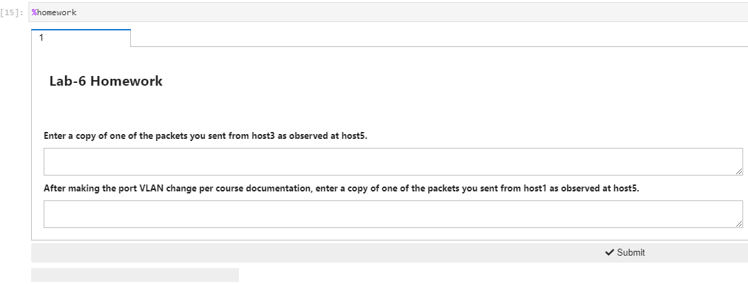
Copy and save this entire packet for the first part of the homework submission.
Step 4
Change the bridge port configuration to add host1 to the same
VLAN as host5:
NET[<bridge-label>][<port-label>].setVLAN(<VID>)
4a. While running tcpdump at host5 and using ethsend, broadcast a packet
from host1:
ethsend --dst-mac ff:ff:ff:ff:ff:ff eth1
4b. Copy the entire packet sent from the host in the previous step as it
was received on host5. Ensure the packet appears correct (i.e. has the appropriate header
information).
4c. In your lab notebook, run:
%homework
in a cell and complete the submission.
Caution
You only have one submission attempt available to you. It is recommended to complete the lab requirements before you load the homework to prevent submitting incomplete data.
Lab Wrap-up
Please follow the instructions to delete your reserved topology and then close and halt your lab notebook and any open terminals on the lab service.