Loops in Ethernet Topologies
Given the simple mechanism that the Ethernet bridges conduct forwarding, it is possible to create topologies that endlessly forward packets in loops without those packets ever reaching a destination.
Plug-and-play operation of the Ethernet bridges provide the means to connect a device anywhere and anytime
Longer distance reachability through the layer 2 networks is allowed through multiple interconnected bridges
Important
Why not plan the deployment of bridges so there are no loops?
The administrative burden on planning the deployment of an Ethernet bridge is minimized by the STP through removal of loops in the resulting network topologies. That is, even if the physical connections between the devices create loops in graphs, the topologies are trimmed to a spanning tree by the STP by pruning selected edges from the graph.
The resulting spanning tree is one of many possible spanning trees that can be created out of a given topology.
A more advanced and in-depth design process would be needed to ensure a specific spanning tree to emerge in this process. Even more planning and design is necessary in order to further ensure a selected set of failover spanning tree options.
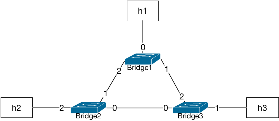
Three Bridges in a Loop
In the case of three bridges in a looped topology, any packet sent from any of the hosts may end up circulating the topology indefinitely.
Note
Why would any loop occur in an Ethernet network topology?
The cables that connect Ethernet-capable devices are typically wired through a routine process in IT organizations.
Since bridges are plug-and-play devices with no pre-configuration requirements, multiple administrator personnel may utilize ports of bridges to achieve the connectivity needs of particular segments of the network in a simultanous manner without an active planning stage. This allows for any end device being added to the existing network. In addition, any bridge device may be moved or added to extend and grow Ethernet network segments. In the meanwhile, a topology or physical cabling diagram may not be present during decisions prior to making the actual connection/wiring happen.
The invention of the successful spanning tree protocol took into consideration the IT processes and how to ease up the deployment processes.
Assuming all bridges start with an empty L2 table:
Bridge1/Bridge2/Bridge3 L2 Table |
|
|---|---|
Port |
MAC |
A packet sent by the host h2 will be flooded by Bridge2 because there is no
matching entry for any destination MAC address.
The forwarding decision at Bridge1 and Bridge3 will also be flood
for the same reason.
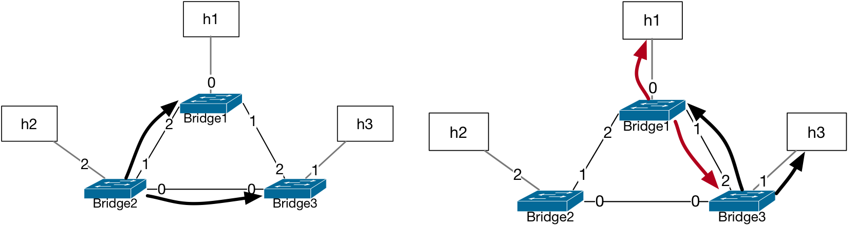
The source MAC address learned by Bridge1 was assigned to port number 2 during
the first flood by Bridge2. When Bridge3 floods this packet, the record at
Bridge1 is updated to port number 1 for this source MAC address from the packet.
Bridge1 L2 Table |
|
|---|---|
Port |
MAC |
2/1 ? |
h2 |
The flapping of port number assignment will happen also at Bridge3 since the
packet is first forwarded to its port 0 (by Bridge2) and then to its port 2
(by Bridge1). Therefore, the L2 tables at Bridge1 and Bridge3 will have
port number assignments for h2 replaced at each forwarded copy of this packet.
Bridge3 L2 Table |
|
|---|---|
Port |
MAC |
0/2 ? |
h2 |
This loop in network topology results in the packet’s constant circulation in the network and the oscillation risk of port assignments to each of the MAC addresses in L2 tables of the bridges.
Tip
Implementation Insight
Modern bridges have provisions against such a flap in the port number for a given MAC address. When a change of port number for the same MAC address value happens at some pre-configured frequency the entry is either locked onto one port index or the packet is discarded for a period of time. Such implementation details are specific to the vendors’ prescribed offerings.
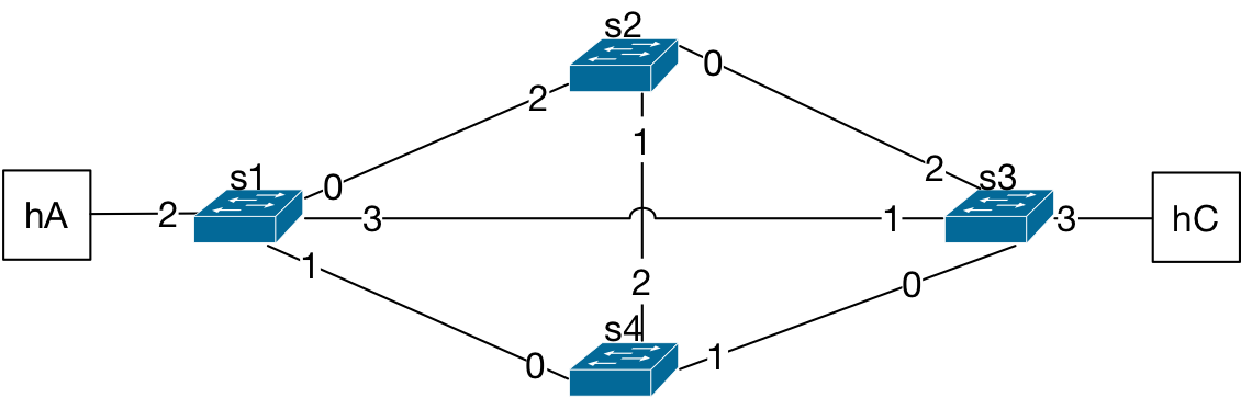
Four Bridges in a Mesh Topology
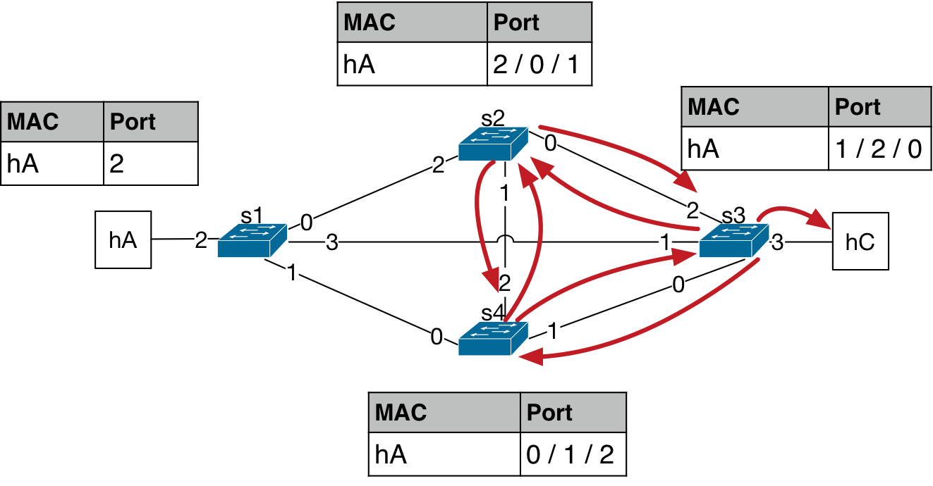
Even more problematic cases of looped topology may happen when there are four interconnected bridges as shown in the figure below, usually referred to as a mesh topology. Just like the case for the three bridges in a loop, let’s assume all bridges have empty L2 tables at the starting point.
The packet from hA is forwarded by the bridge s1 to its ports 0, 1, and 3,
per flood behavior. Now, the MAC address of hA is learned on port 2 for
the bridge s1.
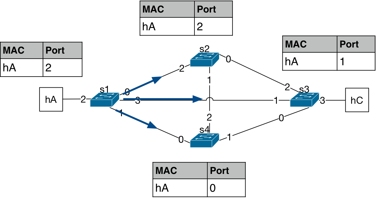
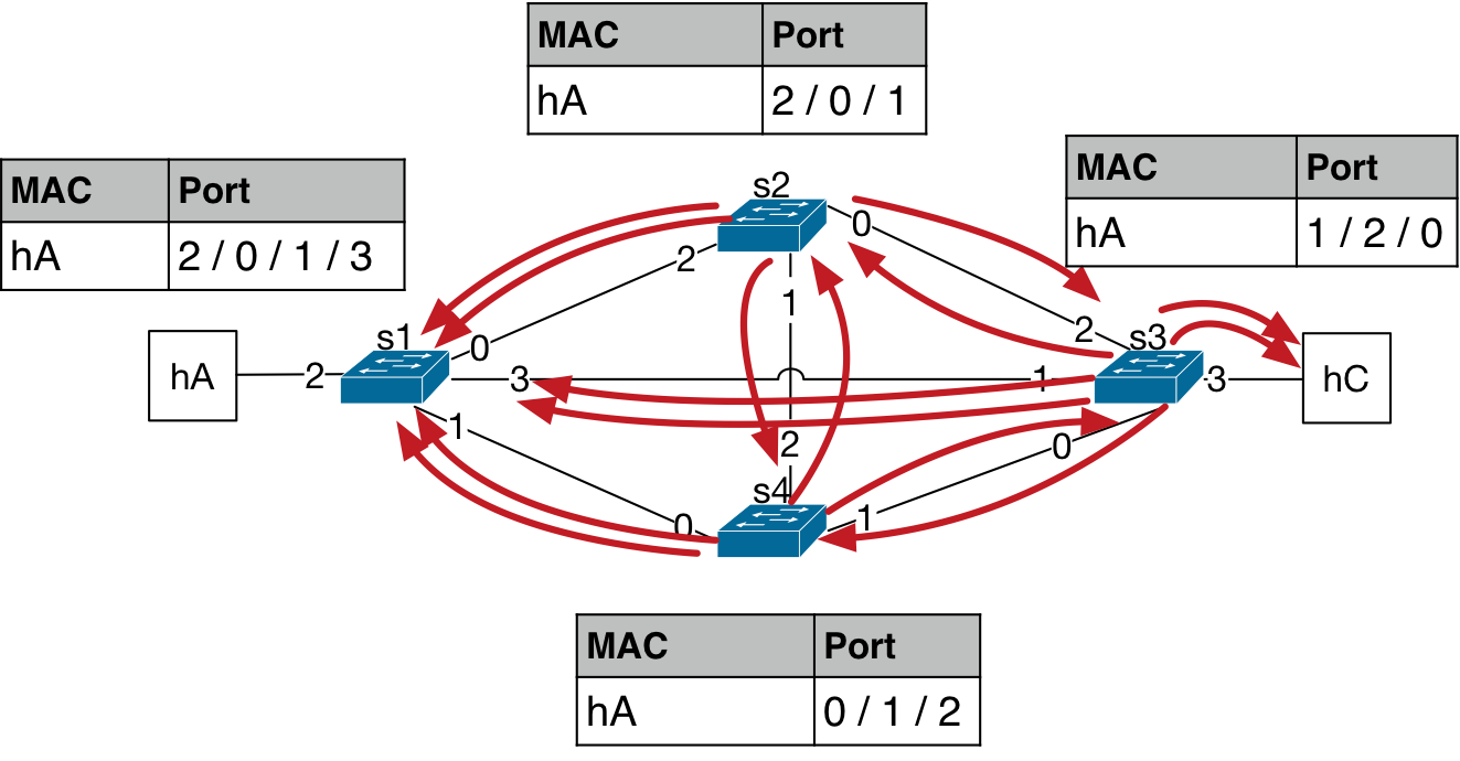
This packet then gets forwarded again by the other bridges in the topology. The three packets turn into seven copies of the packet being forwarded in the next forwarding iteration. And, the MAC address port number starts to flap as the packet is observed at different ports at different time instances.
The process multiplies the number of packets circulating in the network while also making the entries in the L2 tables of the bridges flap each time this packet arrives on a different port. This time the number of copies of packets has reached 14.
Attention
What is the harm in having millions of copies of a packet in an Ethernet network?
The 4-bridge mesh topology forwarding results in an exponentially increasing number of copies of packets circulating in the network. This creates an extra load on the bridges when attending to the packets. First of all, the data forwarding function on the bridges starts to suffer for any other packets that may be sent by other hosts because the bridge is occupied with the existing copies of the packets on its ports. The data transfer load on the links increases as well, eventually, overloading the links with flood packets. The increasing load in this fashion may cause the device to eventually experience a hardware failure.
See also
Recommended Reading List
Interconnections, Second Edition: Bridges, Routers, Switches, and Internetworking Protocols by Radia Perlman, Addison- Wesley, Reading, Mass., 1999, ISBN 0- 201-63448-1.